HTC -- Hitachi HDD Repair Guidance
|
Picture 3.2 label of IDE connection
NV-RAM includes head bitmap data. So PCB of the same series but different model’s HDD is incompatible. In order to make PCB compatible, you can rewrite NV-RAM from the same model HDD (premise is that version number of mask ROM must be matched). You can view PCB firmware version by running “Edit NV-RAM” order in “NV-RAM operation” menu. μ – Code’s form such as: ER2OA41A, among which ER represent HDD department code (refer to table 2, “department code”), 2- represent head number, A41A- represent firmware version number. Besides, you can view ROM firmware version number and version code by “basic information” order.
3.3 Firmware structure and access method of firmware area when breakdown
The same as other brands HDDs, IBM HDD’s firmware is located in disk firmware area alone, it includes many modules. The only greater difference is that PCB board of IBM HDDs used NV-RAM, non-volatile memory; its capacity is 256 or 512 byte. The memory stores module of revise information which correspond to HDD model. Another difference is that IBM HDD use “open” module mechanism, you can read and write so called “open modules” without change to factory module. “Main module table” which MRT Hitachi-IBM read is from USAG module. Besides, “Open modules” table which MRT Hitachi-IBM read is includes fault diagnosis module (It makes no difference to HDD running). All modules store in firmware area according to data of USAG module. Data of firmware area can be divided into 4 types:
— RSVD module, no record in module table; mark the beginning location of firmware area. — USAG table listed module, it is very important to HDD running. — USAG table no listed module, for HDD self-testing. — USAG table no listed “open” module. Running “SA structure test (check firmware structure)” order can read all loaded module. Besides, the order can also check the empty space of firmware area at same time.
You need to pay attention that “open modules” is used another name of modules (such as RDMT module’s name in “open” modules table is RDM1). Functions of firmware module refer to table 4 and table 5
Table 4 main module
Table 5 Open module
Notice: Begin with AVER series HDD, MFGP module appears in “open modules table”; the former model HDD’s “open modules table” is "~@@01.rmp".
Pay attention IBM HDD module have no checksum when analysis firmware, so it is difficult to judge whether firmware structure is damaged or not. If some modules of firmware area are unreadable, you can seek breakdowns by checking firmware structure.
If HDD occurs percussion after read firmware data, troubleshooting by the follow solution:
Unplug control cable of servo system between PCB and HAD, waiting for HDD report ready. Right now HDD can initialize normally from NV-RAM, but it stops loading disk firmware data because of wrong USAG version and it can visit firmware area. Now it can diagnose firmware area (DISK F/W). Use the order of “Batch backup modules” to read out modules one by one, the module which occur percussion is the damage one. Besides, let’s introduce the safety model of IBM HDD. You can use the special jumper to safety model (details in the fourth section). In safety model, it can read or write NV-RAM but can’t operate disk surface. So you can use safety model replace “short circuit method” to revise NV-RAM. It has different effects for different series HDDs to revise firmware in safety model.
So safety model can’t be used to testing and recovery firmware area.
When operate firmware zone, you need to follow the guidance information of the follow two sections: —NV-RAM operation —Firmware zone operation Please refer to follow picture when find breakdown: 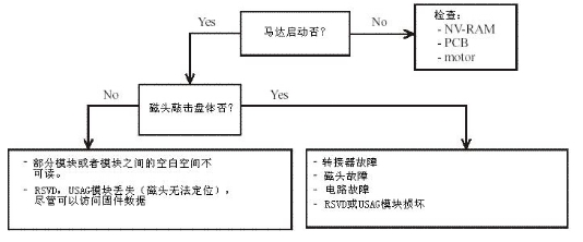 You need to pay attention to the follow points when testing NV-RAM:
—ID must be “E2PR” —Firmware version number and version code must be matched with ROM’s firmware version number and version code Head bitmap must be matched; it can’t have incorrect head bitmap. Besides, NV-RAM includes checksum, if it error, HDD will interrupt loading data. Right now you can copy corresponding NV-RAM data again.
When use “Firmware/Check firmware structure” order to check modules, if some module unreadable, program will report this module is unreadable. Right now you can write in the corresponding normal module. Pay attention that the modules of IBM HDDs have no checksum, so it has a little difficult in judging whether the module is damaged. It is necessary to remain the solution of “RSVD” module damaged. When “RSVD” module damaged, such as head breakdown, it can’t be repaired by the common way. Let’s describe this situation and solution:
Breakdown: HDD couldn’t find firmware and occur percussion, HDD can’t be written in, in other words, all heads are forbidden, moreover: 1) Part of the modules damaged
2) All modules damaged 3) All heads can’t read data Reason: RSVD module damaged, RSVD’s mark is in the primary location but data is invalid. Solution:
• Set up driver to safety module (or for DJNA, DPTA model, unplug servo system cable), revise head bitmap—use another head (try head 1) to replace the primary head 0, recreate boot program. Then jump the jumper to normal model, turn the power, waiting for HDD reporting ready. You can also check NV-RAM. • Run boot program to redistribute heads.
• HDD should report ready, but appear the information of “modules table unreadable”. • Clear up firmware area data. • Turn off HDD power and then turn on, clear up firmware area data. Pay attention to: →Rewrite NV-RAM, RSVD, USAG modules
→Rewrite other modules →Run boot program to write in module (not the boot program which change head bitmap, but the write module one). This operation could make sure modules are written correctly. • Rewrite PSHT, RDMT
• Turn off HDD power and then turn on. Pay attention to: →Clear up firmware area →Rewrite RSVD, USAG →Rewrite other modules →Run boot program to write in modules • Rewrite PSHT, RDMT Warning! Arrowed operation must be completed once; it couldn’t restart computer or program halfway. 3.4 Key module
The follow modules are the key modules for IBM HDDs: PSHT, RDMT, SRVM, ZONE, and CNSL. Moreover, NV-RAM head bitmap data should be correct. 4. Explanation of IBM HDDs department
HDDs department is classified according to their structures and repair ways. 4.1 Explanation of 1.22GXP (DJNA7), 34GXP (DPTA7) and 37GP (DPTA5) series HDDs 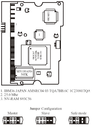 Picture 4.1 DJNA series HDDs circuit board
Above series HDD’s PCB uses two kinds of ROM:
A mask ROM which integrate within the main chip, includes execute codes and default settings. Another is serial flash ROM—NV-RAM. It includes setting parameter of visit disk firmware. The model is S93C56 and capacity is 256 byte.
When processing element breakdown and have no HAD, HDD couldn’t report ready.
Hitachi-IBM program will have information when booting
“Read NV-RAM…………………………………………Error(Read NV-RAM error)”.
If main chip normal, although it hasn’t HDA, HDD can report ready, too. (DRDY and DSC of status register will light.)
If firmware module unreadable, it will show information:
“Read module table…………………………………………Error(Read module table error) ”
and
“Read ZONE…………………………………………Error(Read ZONE module error).
If head can’t located and have no percussion, it most likely its module data damaged. Right now you can run “SA structure testing (check firmware structure)” order to checkout which module is damaged. If module is readable but module contents are incorrect, you can use “write module” to rewrite module.
There are many kinds of firmware versions of main chip ROM. If it matched firmware, it is compatible. Besides, the last two characters of version number may different. Different series HDDs’ PCB can’t replaced by each other, because they use different mask ROM and servo control chip. If replace PCB in the same version main control chip ROM which have different head number, you should clear up NV-RAM contents. Because you can read/write NV-RAM alone without HDA, so you should disconnect the connection cables of servo system and waiting for PCB reports ready.
If one or more heads damaged, heads will keep knocking disk body. If heads are normal, knocking is caused by firmware data, HDDs will report ready after occur percussion.
Explanation of 4.2.40GV ( DLTA5 ), 75GXP ( DTLA7 ), 60GXP ( AVER ) and 120GXP ( AVVA0) series HDDs.
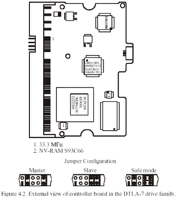 Picture 4.2 DTLA-7 series HDD circuit board
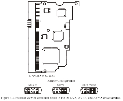
Picture 4.3 DTLA-5, AVER and AVVA series HDDs circuit board
The earlier model HDDs have two heads (sometimes it may has one head of factory restored HDDs). The most have five heads. These series HDDs use glass disks, which have smoother surface than aluminum disks.
There are three kinds of ROM chips in PCB:
—Mask ROM integrated in processing element. It includes execute code and the default settings. —Serial Flash ROM — NV-RAM. It includes setting parameter of visit disk firmware area. The model is S93C56, the capacity is 512 byte. —ROM chip, not all PCB has it. This Flash ROM replaced mask ROM storing firmware data, it is used to testing samples (allow revise fault code). The socket of chips is located near NV-RAM. The model is 25FV101T and capacity is 1M byte. Different from the former series HDDs, the damage of data in NV-RAM will cause PCB stop work and couldn’t report ready. In this situation, you can the method of 3.3 “Firmware structure and access method of firmware area when breakdown” to make HDDs not knock anymore and report ready. Then you need to rewrite NV-RAM.
The phenomenon of module damage is the same as 4.1. The heads of these series HDDs may not lie on disks, but lie on the outside border of disk—a kind of frame made up by special synthetic material. This way may scratch disk because head bend when enter or quit. The head will frequently "sticky" on disk, too.
If disk defects disappear in writing process, you can use “factory formatting” order repair. It doesn’t rewrite the whole HDD space any more, so it is fastest. It takes 25 minutes for AVER series 40GB HDD.
Sector damage is mainly caused by the poor connect between the connection of PCB and HDA. The connection between each other is completed by the plug which near the power plug under PCB board, but the HDD’s PCB assembly is not strong, mechanical shift or thermal deformation will lead Tin shed of the plug. Therefore, you should re-weld before revise.
4.3 Software repair
4.3.1 Identification and solution of defects in user’s area MRT Hitachi-IBM program could write defects into G list or edit G list by hand (RDMT). For insignificant damage, it is easy to deal with defects: If it is caused by poor connection, please refer to “IBM HDD circuit board breakdown” 1). Formatting. If finished normally, it indicates no serious damage.
2). Running logical scan, write defects into G list. It couldn’t use physical parameter to write defects into defects table automatically. 3). If has defects, recreate translator. In this process, G list’s defects will be written to P list and then clear up G list. Pay attention that defect candidates won’t be written to P list from G list, because HDD regards defect candidates as unstable region. If you want to write defect candidates into P list, please enter into RDMT translator (menu “tools->LBA defects table translator”), write defects into P list according to cues and the work of recreate translator will be done automatically.
4). Run logical scan again, if find defects, repeat step 3.
Factory formatting order can operate local servo region, then write defects into “cylinder table”. After revise “cylinder table”, you need to clear up P list and G list, because right now the defects record of P list and G list are invalid. Besides, the defects which not be added to G list automatically can use inner editor to add in G list by hand. After edit G list, program will recreate translator automatically. You can also load defects table which found by “formatting” in defects table.
4.4 Features of software repair
When firmware data damaged, HDD usually continue to knocking heads, waiting and so on. That is to say, it makes software repair unrealizable. In this situation, you need to prevent HDD loading firmware data from disk firmware area but persist the function of visit firmware area. You can achieve the purpose by revising head bitmap of NV-RAM and revising firmware version number. Notice: In safety module, you can only read/write NV-RAM and can’t operate disk surface. 5. Auxiliary file
File name is chose by users, but extend name is designated by program according to type: *.tsk — Task file, use to test save settings of model automatically; *.bin — ROM firmware file, build when read ROM; *.nvr — NV-RAM firmware file, build when read NV-RAM; *.rpm — HDD’s firmware module. 6.Circuit board breakdown
Introduction of electronic components which may lead breakdown. Beyond question, the most troublesome part is connector between circuit board and HDA. PCB’s fasten of all series IBM HDDs is unreliable, so mechanical shift or thermal deformation will lead solder off of connector. This causes numerous “phantom” bad sectors, even the damage of disk firmware. You need to re-welded connector before repair. Then you can clear up “phantom” bad sectors by using logical parameter to formatting. Ceramic filter near the 35th needle of microprocessor and IDE interface can use oscilloscope to test IDE interface, breakdown led by welding quality, breakdown led by low impedance transmission resistance nearby and the power supply element such as voltage stabilizing circuit and coil. There is no individual voltage stabilizing chip. Voltage stabilizing function is realized by voltage stabilizing unit of servo system and voice coil control chip. If voltage stabilizing circuit breakdown, the voltage will rise from 3.3V to 5V. It will not only burned circuit board components but also damaged adapter in HDA. If you want to recovery data from this HDD, you need to change head assembly.
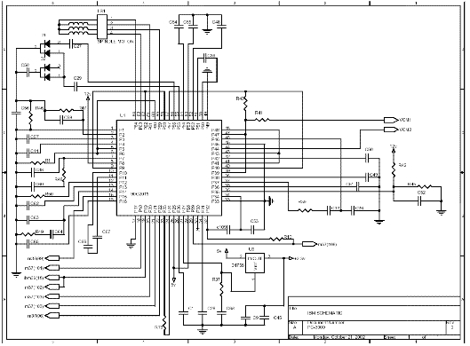
7. Circuit diagram
7.1 The layout of the components 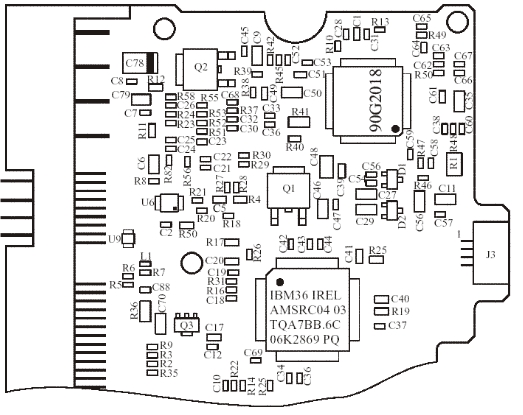 7.2. Circuit diagram
|