
HTC -- Hitachi HDD Repair Guidance
|
--Code of microprogram version
--Heads map(Such as 00 01 02 03)Head number and their connection of HDD.
SA structure checking (check firmware structure) Check the firmware integrity and their contents for damage.
Information of modules is showed in the program Log page in the form of log. “Backup module object” This order can repair a single or a group module. The order also allows reading modules in varies model: Ignore errors when read modules. Copy 0
Copy 1
Copy F (Copy factory)
“Copy 0” or “Copy 1” model only read module copy 0 or copy 1. Copy 1 is corresponding head 1 in multiple heads HDD; copy 1 located in another track in single head HDD. The exact location of module copy is stored in address byte of NV-RAM. If write data of multiple heads HDD into NV-RAM of single head HDD, it will lead to knock on disk-----HDD tries to find module copy of corresponding head which is inexistent. When only copy 0 breakdown, some module includes incorrect data or it needs to read some data of module from some copy, read another data of the same module from another copy, this module is very important. Disk rotation will lead to the module breakdown of copy 1 extend to adjacent track, right now you can use hexadecimal translator stitching recovery data read from module 0 and module 1. Before that, you should select “ignore error when read modules” model. Warning! Not all modules have a copy in copy 1, so they can only use “Copy 0” model. They listed in “open modules table”, but the module which doesn’t listed in “modules table(USAG)” couldn’t use “copy 1” model.
“Copy F (copy factory)” is transfer factory write module into unused tracks of HDD. Warning! Only listed in “modules table”, the module can use this function. Moreover, SRVM module’s copy factory is different from the actual used module in revise part. It is obvious that after write “copy factory” of SRVM module into HDD and through the finally revise, it causes the different between two modules.
2.3 “Revise configuration” order
If some original modules unreadable, it could copy the corresponding module from HDD of same model. We need to pay attention that the module copying from other HDD, it needs execute revise process again according to revised head configuration. The modules which need to revise are ZONE, SRVM and CNSL. All modules may also unreadable when head 0 breakdowns. “Change the head of bitmap” is only revising data of NV-RAM to change head of bitmap. When firmware area has defects sectors, you can use this way to repair HDDs.
“Revise boot identification” is zero clearing boot identification of NV-RAM. When firmware area breakdown, it leads to HDD boot suspended or head hammering. You can use this order to visit firmware module of HDD. This way is like an “on-off”.
2.4 Recreate translator
“G-List to P-List” is write defects of G list into P list. Due to this order is operating translator, it will ignore so called “candidate” defects (unstable sectors). 2.5 Drive ID
Drive ID, revise drive ID (drive ID is read by system BIOS when PC booting), check whether the information of firmware area is correspond to the information of HDD label.
2.6 Formatting
Formatting, recreate translator, cover the surface of HDD rapidly by random code of sector buffer. Interrupt it when meet badly damaged region. When run this order, you need to fill in the begin LBA address and finish LBA, formatting step numbers. Skipped the maximum number of sectors when meet errors and continue. Besides, you can choose whether to record defects. If you choose record defects sectors, it will show defects sector table after finishing formatting. 2.7 Logical scan
Logical scan is use logical parameter to scan the surface of disk and store defects in file. HDD writes bad sectors into G list. After finishing scan, it will show defects articles, you can edit defects file by hand and write defects into G-List (RDMT) by hidden defects operation, finally execute G-List to P-List to write defects of RDMT into PSHT, after this operation, RDMT will be emptied. 2.8 Defects table
Warning! Program can only display maximum contents of 65,535. If G list includes more than 65,535 records, the excess will not show. But in the beginning, the numbers of total defects are correct. 3. Firmware
3.1 IBM HDD firmware structure IBM HDD firmware includes three parts: parts of ROM, configuration data of NR-RAM and loading data of disk firmware area (DISK firmware). Firmware has version number and version code. Version number is developing procedure and version code is project code. Firmware which store in mask ROM can be revised. The revised part of firmware is store in NV-RAM and DISK F/W. IBM’s engineers provide a way to distinguish firmware version: version number changed but version code same. For example, firmware which version number is A46A, after upgrading, it changes to A4XX, the first two characters is the same but the latter two changed.
Notice: Firmware of different series HDDs can’t replace.
When meet follow terms, firmware is compatible: —ROM, NV-RAM and DISK F/W have the same version code
—μ – code of NV-RAM and DISK F/M are matched —ROM version number and NV-RAM and DISK F / W version number only have the latter two different characters. 3.2 Compatibility of PCB
PCB’s compatibility can be identified by the label of IDE connection (refer to picture 3.1, PIDM module has same contents). If the first character of the first two lines is same, the PCB is compatible and can be exchanged. More exact distinguish way is refer to information of ROM or NV-RAM. (Due to the data of NV-RAM may be damaged or rewritten, so information of ROM is more dependable) 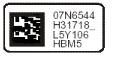
|