MRT Western Digital Professional Tools Instructions
These documents are derived from MRT Firmware Laboratory.
For more information, please visit our website http://www.mrtexp.com
Content
1. Startup Interface
1.1Select HDD model dialog box………………………………………………2
2. Main Interface
2.1 Menu and Main Functions…………………………………………………..5
2.1.1Dianosistic Menu…………………………………………………….5
2.1.2 Service Area Operation…………………………………………..…16
2.1.3 Tools……………………………………………………………….....30
2.2 Toolbar……………………………………………………………………..35
Startup Interface
1.1 Select HDD Mode Dialog Box
Select HDD Mode Dialog Box,as shown in figure 1.1-1
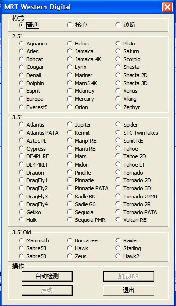
Figure1.1-1Mode Selection
The dialog box lists versions and program startup model (the default startup model is the common model) supported by Western Digital(hereinafter refer as WD). Users can manually select the model or automatically detect, after selecting the model, click “Startup” button to enter the main interface of WD Professional Tools.
“Common Model” is used to normally visit HDD and each module can be normally opened .
If under “Common model ”, HDD can’t normally ready or can't read the information of ROM, RAM and other models, users can select “Key Model”or "Diagnostic Model" according to practical situation. Under the two models, the program will carry on the special treatment on HDD; the program will enhance the processing capacity of HDD failures.
Under“Key Model”, HDD disk stops running, at this time you can only visit the module information on PCB board, and can't visit the contents on HDD disk. If users choose this model, the program will pop up “Input SASPT” dialog box in the process of its initialization (as shown in figure1.1-2), users can operate HDD under this model after setting SASPT.
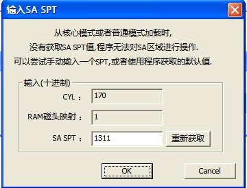
Figure1.1-2Input SA SPT
“Diagnostic Model”is MRT Firmware Laboratory to develop the repair function for WD Series HDDs, when HDD can’t normally ready, users need to manually “short circuit” HDD Safe Jumper. Then when the program starts , select “Diagnostic Model”, click “Automatic acquisition model”or Manually select the model, after starting the program , users are required to set up working folder to save model information(as shown in figure 1.1-3 ) so as to recover initial statue of HDD when errors occur.
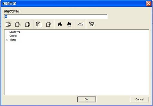
Figure1.1-3Save Module
Please refer to “MRT Main Program Instruction”, if you want to know more information about MRT Directory Structure. After saving the information of modules, it will pop up the dialog box as shown in figure 1.1-2 to ask users to input SASPT, the default SASPT information is automatically acquired by program, users can also manually input. After setting SASPT, click “OK” button, it will pop up the prompt information (As shown in figure 1.1-4).
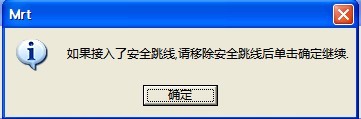
Figure1.1-4 Prompt Information
If users connect the security jumper before starting program, then users need to remove the security jumper to make sure the program work normally.
Click “OK” button to enter “Diagnostic Model”, the program will re-start HDD and set information inside RAM. This moment users can normally read HDD Firmware Information, including ROM, RAM on PCB board and CP List, Module List and other information on HDD disk. Users can observe the startup situation on Log Page.
Main Interface
The Main Interface of WD Professional Repair Tools, all the operations by users will be recorded in log page, as shown in figure 2.
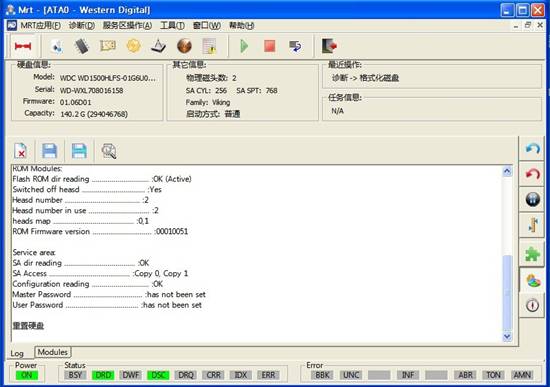
Figure2(WD Main Interface)
2.1Menu and Main Functions
WD Professional Tools Main Functions are mainly concentrated on the "Diagnosis", "Service Area Operations", "Tools" three menus; each menu structure as follows:
2.1.1 Diagnosis
1. HDD Information
“HDD Information”submenu can display the current basic information of HDD in the form of the dialog box, and it can detect HDD again. As shown in figure 2.1-1.
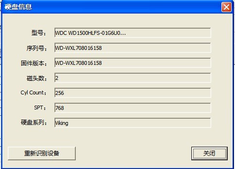
Figure 2.1-1(HDD Information)
2. ROM-related Functions
“Diagnosis—ROM-related Functions, as shown in figure 2.1-2.
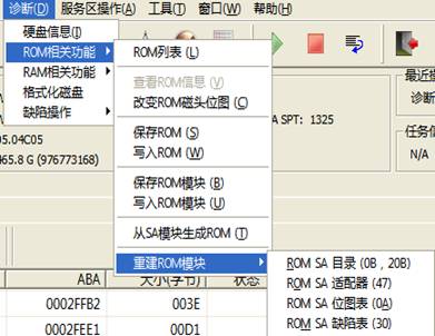
Figure 2.1-2(Diagnosis—ROM-related Function)
“ROM-related Function”submenu provides the basic operations to ROM, including "Show ROM List" (Figure 2.1-3), "Save ROM", "Write into ROM", "Save ROM module", "Write into ROM module" and other series of operations.
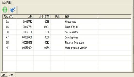
Figure 2.1-3(ROM List)
Double-click any line in the ROM List to load ROM into Hex Editor(as shown in figure 2.1-4), in the Hex Editor, ROM information will be displayed as hexadecimal form, from left to right is Offset, Hexadecimal information, ASSII code, users can edit the contents inside ROM.
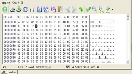
Figure 2.1-4(Hex Editor)
After the completion of editing, users can select to write into HDD directly or save it to the file to load it to the previous saved file.
It will pop up “View and Edit HDD resource” dialog box when users click “View and Edit HDD resource” button. Please refer to “Tools-Common Tools- View and Edit HDD resource” for more detailed information. Users can view each HDD module and editable resource.
3. Change Head Bitmap
“Change Head Bitmap”(As shown in figure 2.1-5)dialog box lists the number of heads among the current HDD, users can choose to kill which head according to their own situation, once one head is killed, it will lead to the reduction of HDD capacity.
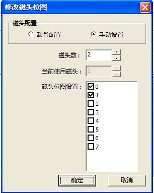
Figure 2.1-5(Change Head Bitmap)
When users need to save “ROM information”, “Module information”, “RAM information” and other HDD firmware information, if users has not create the save directory of HDD model, it will appear the following dialog box. As shown in fogure2.1-6
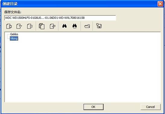
Figure 2.1-6(Save HDD firmware information)
The default save path D:\UserDataFile,under this file, MRT by default set up a file for each MRT professional tools. For example:Disk copy tools, the default folder DataCopyer;WD professional repair tools, the default folder WDCMarvel etc. In each folder of professional tools, it sets up the folder to each kind of model; Folder naming rules consists of HDD manufacturer - model - serial number. In the dialog box, users can see the existed folder, and can operate the folder through the toolbar on the dialog box. When users have already set the save path, click “OK” button, it will pop up “Firmware Description ” dialog box(as shown in figure2.1-7), users can add an remark here providing convenience for the next view.
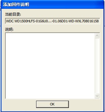
As shown in figure 2.1-7(Firmware Description)
Click “OK” button, it will pop up “Save As” dialog box (as shown in figure2.1-8), at this time users can save the specified module resource. If users have already set the working directory before, the dialog box of “Save HDD Firmware Information” and “Firmware Description” won't appear, it directly appears the dialog box “Save As.”
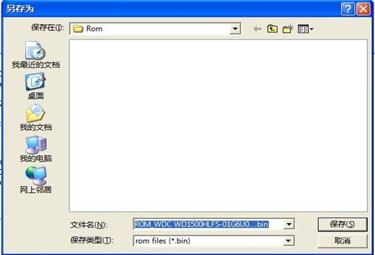
Figure 2.1-8(Save As )
4. Save ROM Module
“Save ROM Module”is used to save all the current ROM modules resource inside HDD, as shown in figure 2.1-9.
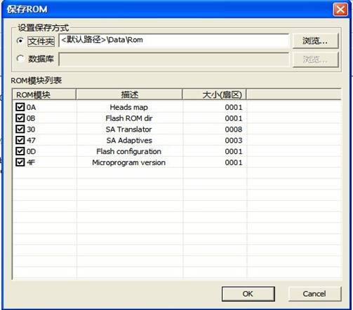
Figure 2.1-9(Save ROM Module)
5. Write into ROM Module
“Write into ROM Module”is used to write the previous saved ROM module into RAM chip of HDD(as shown in figure2.1-10), the dialog box lists all the current ROM modules of HDD, working directory and working directory structure.
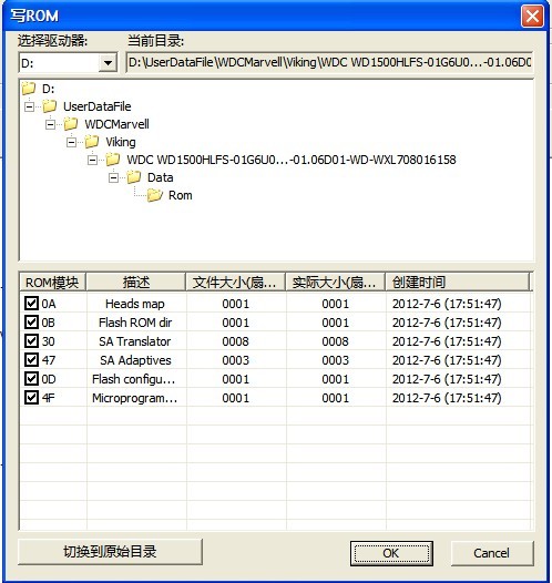
Figure 2.1-10(Write into ROM module)
6. From SA module to generate ROM
“From SA module to generate ROM”(as shown in figure2.1-11),when we replace HDD circuit, HDD can’t work due to the mismatch problem, this function is used to write the corresponding ROM information into HDD motherboard chip.
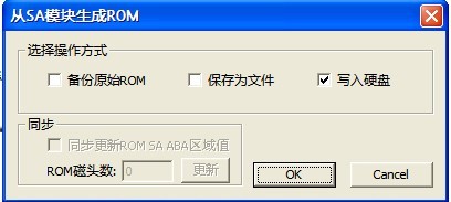
Figure 2.1-11(From SA module to generate ROM)
7. Rebuild ROM Module
“Rebuild ROM Module”menu can be divided into four menus: "ROM SA Directory (0B, 20B)", "ROM SA Adapter (47)", "ROM SA Bitmap Table (0A)", "ROM SA Defect Table (30)" . It can be rebuilt according to different ROM modules, please refer to “Tools-Common Tools- View and Edit HDD resource” for more detailed information about ROM.
(1)ROM SA(0B,20B)
“ROM SA(0B,20B)“submenu is the rebuilding 0B, 20B module, the rebuilding results will display in the log page.
(2)ROM SA Adapter(47)
“ROM SA Adapter(47)” submenu is used to rebuild ROM 47 module, users can select to back up the current ROM, they can also save the rebuilding information as the file, as shown in figure 2.1-12.
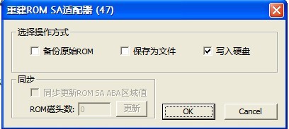
Figure 2.1-12(ROM SA Adapter(47))
(3)ROM SA Bitmap Table(0A)
“ROM SA Bitmap Table(0A)“(as shown in figure 2.1-13)submenu is used to rebuild ROM 0A module,users can select “Automatic Generation” or “Manual Generation”, the former uses the default number of heads, the later needs to manually configure the number of heads, please refer to “Change Head Bitmap”(Figure2.1-14)for more information about head modifying.
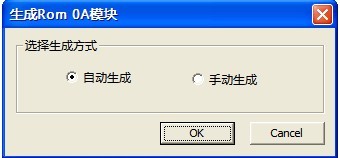
Figure 2.1-13(ROM SA Bitmap Table(0A))
(4)ROM SA Defects Table(30)
“ROM SA Defects Table(30)” as shown in figure 2.1-14.
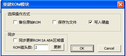
Figure 2.1-14(ROM SA Defect Table(30))
8. RAM-related Functions
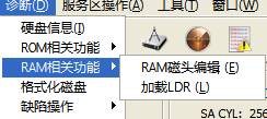
Figure 2.1-15(RAM-related Functions)
“RAM-related Functions” menu has two submenus: "Edit RAM Head " and "Load LDR".
(2)Load LDR
When HDD can’t start by using conventional way, it can start from outside files, at this time loading LDR can realize the effect, as shown in figure 2.1-16.
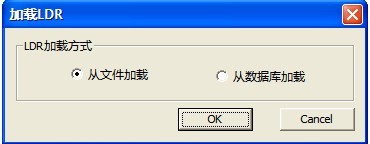
Figure 2.1-16(Load LDR)
9. Disk Formatting
“Disk Formatting” operation is used to format HDD, there are many ways for users to choose, as shown in figure 2.1-17.
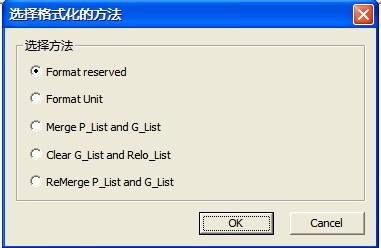
Figure 2.1-17(Disk Formatting)
These methods of formatting are available for you to select:Formatting Reserve, Formatting unit, Combine P-List and G-list、Clear G-List and Relo-List、Combine P-List and G-List again. After selecting the method of formatting, click “OK” button to execute.
10. Defects Table
Defects Table is used to record the defect areas in HDD, can be divided into the following types of defects:P-list、G-list、T-List、SA-List.
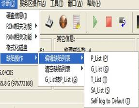
Figure 2.1-18(Diagnosis—Defect Operation)
(1)P-List,permanent defect list:these defects are found by manufacturers to use specialized test equipment. These defects are permanent defects generated by the magnetic medium after life comes to the end. These defects cannot be canceled for the non-manufacturers; they can only use some special equipment to increase it. There is no need to take care of it because G-List exists, so the list of G-List inside disk is not empty when some manufacturers have sold this product recently.
(2)G-list,Growth Defect List:The defects can be found in the process of operation HDD, can be found in the process of formatting, or can be found in the process of using REASSIGN BLOCK command to do reallocation.
(3)T-List,Track Defect List
(4)SA-List,Service Area Defect List:
Users click one defect table under “Editing Defect List”menu, the program will list all the defects recorded in this defect table, as shown in figure 2.1-19.
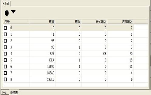
Figure 2.1-19 Edit Defect Table
Double-click any line in the Defect Table; you can edit the defects, as shown in figure 2.1-20.
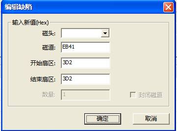
Figure 2.1-20 Edit Defect
For similar operation on other defects, we won’t explain one by one.
“Clear Defect Table”will clear HDD defect recorded in the corresponding defect table, when users perform this operation, it will remind users to save the current defect, the execution results and the save information will display in the Log page.
2.1.2 Service Area Operation
“Service Area Operation” menu structure as shown in figure 2.1-21
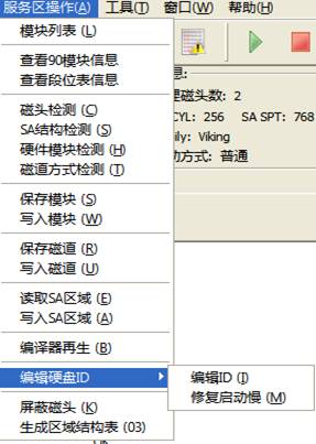
Figure 2.1-21(Service Area Operation)
1. Module List
“Module List”submenu displays the current module information, as shown in figure 2.1-22.
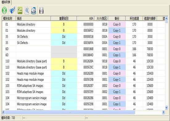
Figure 2.1-22(Module List)
Users can click the right-click in the list box, it will pop up “Right-click Menu”, as shown in figure 2.1-23. Double-click any module; you can load this module into Hex Editor to edit, as shown in figure 2.1-26.
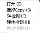
Figure 2.1-23(Right-click Menu)
Click “Open” button to load this module into Hex Editor Page; Click “Select Copy”, it will copy number 0 backup or number 1 backup of this module, as shown in figure 2.1-24;Click “SA Detection”button, it will detect HDD service area, the detection content contains whether service area can read, whether service file is normal, whether the calibration is correct.
The detection result will display in the last several pages of “Module List”, as shown in figure2.1-25;“Hardware Detection”, it will detect HDD firmware, the detection content contains Copy 0 and Copy 1.
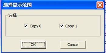
Figure 2.1-24(Select Copy)
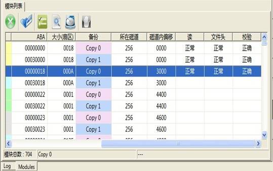
Figure 2.1-25(SA Detection)
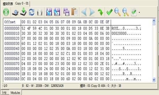
Figure 2.1-26(Hex Editor Page)
Users can perform the operation on this module according to the toolbar provided by Hex Editor, including modification, write, save, search etc. You can also click the right-click in the list box and select the operation in the pop-up menu, as shown in figure2.1-27.
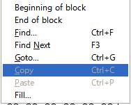
Figure 2.1-27(Right-click Menu)
2. View 90 Module Information
“View 90 Module Information”provides a view with the save information of 90 module, the result will display in the Log page, as shown in figure 2.1-28.
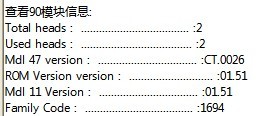
Figure 2.1-28(View 90 Module Information)
The content of displaying contains the total number of heads, the current use of heads, Mdl 47 Version, ROM Version, Mdl 11 Version, and Family Code.
3. View Zone Table Information
“View Zone Table Information” will display HDD Zone information, because of the reason of publishing, we only intercept part of results, as shown in figure, 2.1-29.
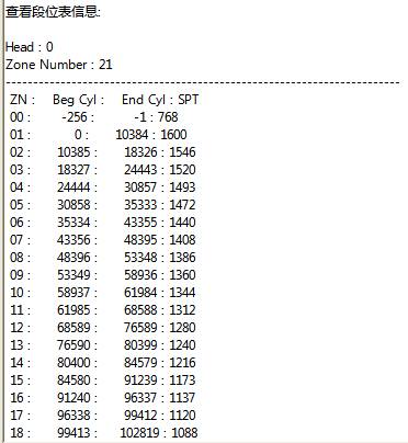
Figure 2.1-29(View Zone Table Information)
4. Head Detection
“Head Detection”(Figure2.1-30)can read, write detection of heads, the detection result will display in log page(Figure2.1-31).
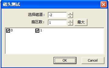
Figure 2.1-30(Head Detection)
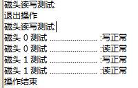
Figure 2.1-31(Detection Result)
5. SA Structure Testing
“SA Structure Testing”(Figure2.1-32),the testing result will display in the “SA Testing Result” page(Figure2.1-33).
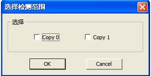
Figure 2.1-32(SA Structure Testing)
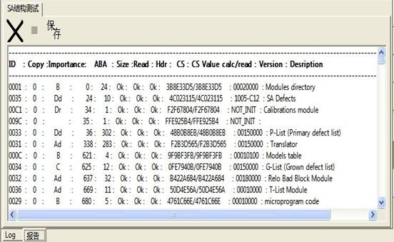
Figure 2.1-33(SA Structure Testing Result)
“Hardware Module Detection”will detect the information of hardware modules, the result will display in the “Report” page(Figure2.1-34).
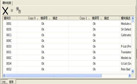
Figure 2.1-34(Hardware Detection)
“Track Way Detection”refers to 2.1.2 -7“SA Structure Detection”.
8. Save Module
“Save Module”refers to 2.1.1“Change Head Bitmap”(Figure2.1-3).
9. Write into Module
“Write into Module ”as shown in figure2.1-35.
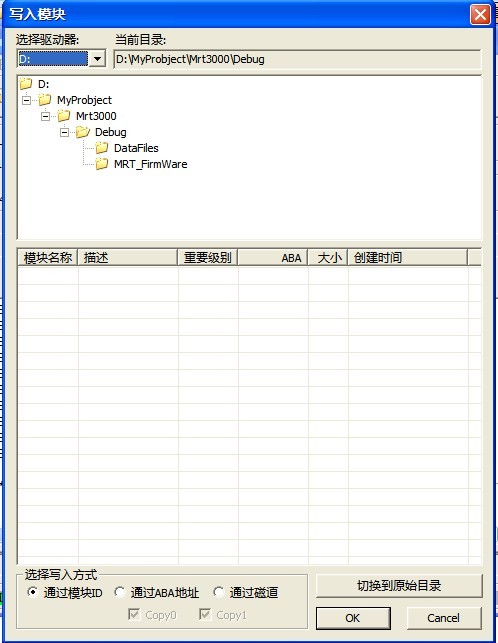
Figure 2.1-35(Write into Module)
Users can choose the way of writing into, if there are files of module information in the specified list, the information of files will display in the list box, otherwise it will display in the blank list. After setting the module of writing into by users, click “OK” button to finish this operation, the operation result will display in the Log page.
10. Save Track
“Save Track”as shown in figure2.1-36.
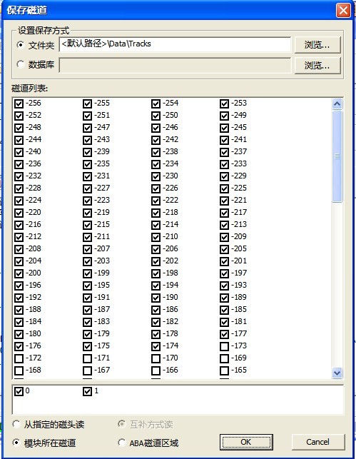
Figure 2.1-36(Save Track)
Users can select the tracks need to be saved and the way of saving as well as set the save path. Click “OK” button to complete this operation, the operation result will display in the Log page.
11. Write into Track
“Write into Track”will write the files saved by users into the specified track, as shown in figure 2.1-37.
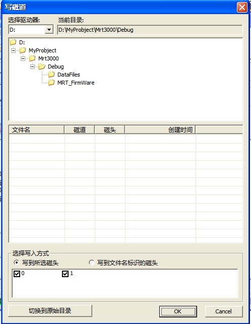
Figure 2.1-37(Write into Track)
If there are the files of module information in the specified list, it will display in the list box, otherwise it displays the blank list.
12. Read SA Area
“Read SA Area”provides the operation of reading on the service area, if users has not set the save path, it will pop up “Creating Content” dialog box, please refer to 2.1.1 for more detailed information about setting. It will appear “Save SA Area” dialog box when users has already set the working directory, which requires users to set the save directory(as shown in figure2.1-38).
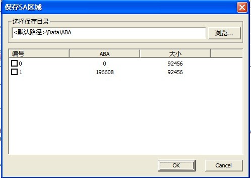
Figure 2.1-38(Save SA Area)
After the completion of setting, click “OK” button to begin to perform this operation, the operation result will display in the Log page.
13 Write into SA Area
“Write into SA Area”(as shown in figure2.1-39)
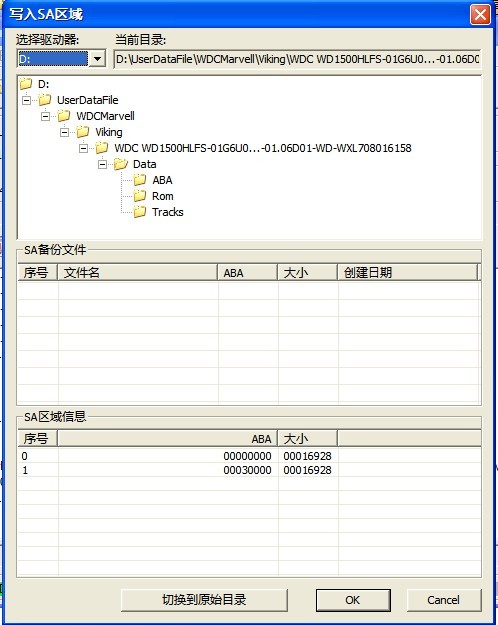
Figure 2.1-39(Write into SA Area)
14. Regeneration of Translator
“Regeneration of Translator”please refer to 2.1.1“Disk Formatting”.
15. Edit HDD ID
“Edit HDD ID”can be divided into two submenus: “Edit ID”(as shown in figure2.1-40)、“Repair slow start(as shown in figure2.1-41)”.
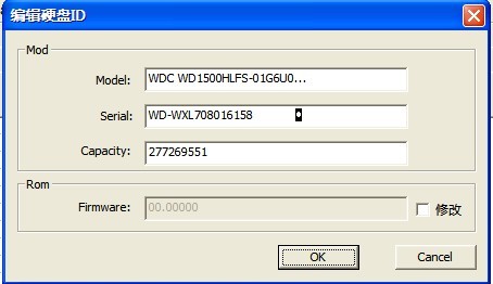
Figure 2.1-40(Edit ID)
There are these options of model, series number, capacity to modify, and it also provides modify ROM Firmware, click “OK” button to complete the modification.
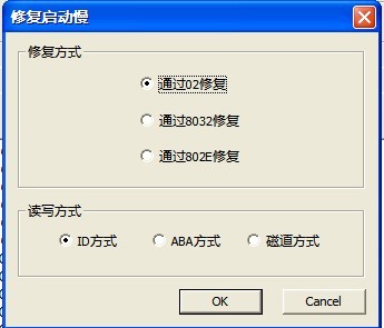
Figure 2.1-41(Repair Slow Start)
16. Kill Head
“Kill Head”(As shown in figure2.1-42)
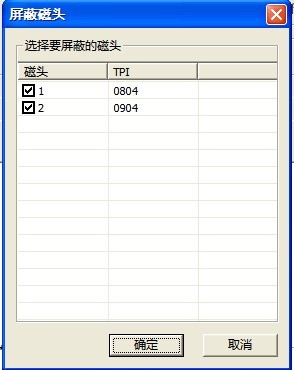
Figure 2.1-42(Kill Head)
17. Generating Area Structure Table
2.1.3 Tools
“Tools”menu structure as shown in figure 2.1-43.
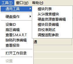
Figure 2.1-43(Tools)
1. Universal Tools
“Universal Tools”menu can be divided into six submenus:“Module List”、“Search Module from SA”、“View and Edit HDD Resource”、“Edit Module Directory”、“Self-calibration Test”、“Adjust Adaptive Parameter”
(1) Module List
“Module List”please refer to 2.1.2(module list).
(2) Search Module from SA
“Search Module from SA”, search module from service area, the search result as shown in figure 2.1-44.
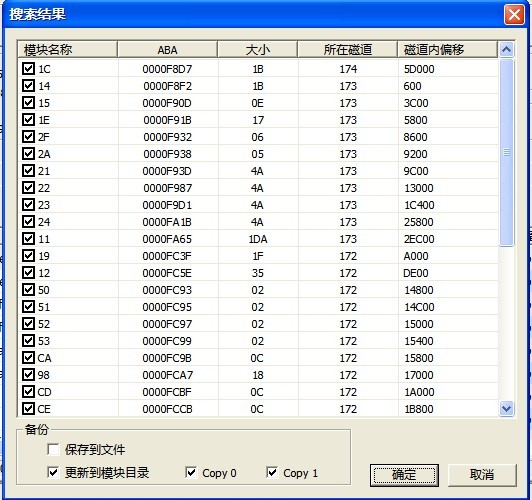
Figure 2.1-44(Search Result from SA)
When HDD can’t normally acquire the module directory table, using this function can rebuild the module directory table.
(3)View and Edit HDD Resource
“View and Edit HDD Resource”(as shown in figure2.1-45),can view“Track”、“Module”、“ROM”、“RAM” and other HDD Resource. The operation result will be recorded in the Log page.
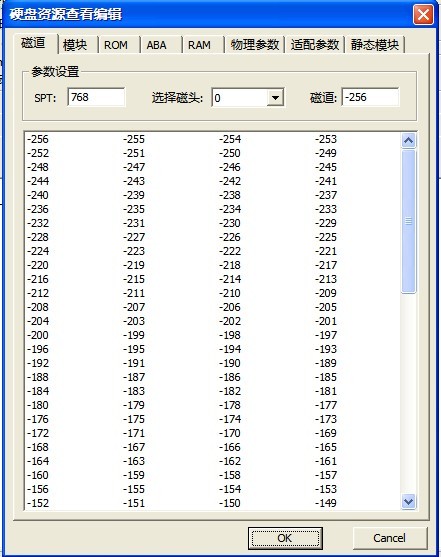
Figure 2.1-45(View and Edit HDD Resource)
Expect RAM module, double-click one item in any module list, this module can be loaded into Hex Editor, users can modify this module, write this module into disk, save this module and other operation on Hex Editor. Please refer to 2.1.1-2“ROM”for more detailed information about Hex Editor.
(4)Self-calibration Test
“Self-calibration”as shown in figure2.1-46,
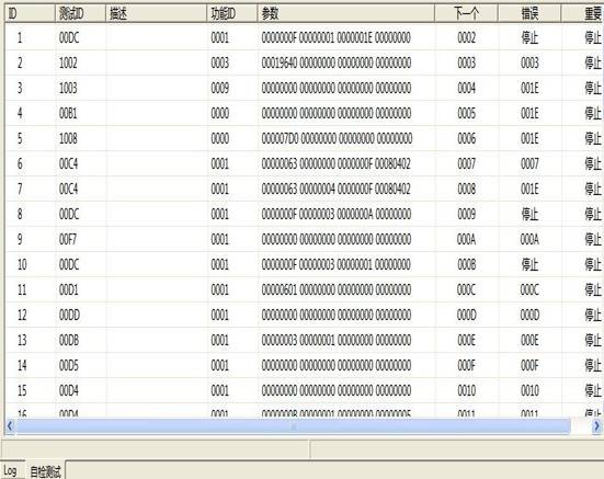
Figure 2.1-46(Self-calibration Test)
(5)Adjust Adaptive Parameter
2. HDD Operation
“HDD Operation”menu has four submenus:“Reset”、“Standby”、“Soft Reset”、“Hard Reset”. Please refer to 《Main MRT Program Description》 for more detailed information about these four operations.
3. Device ID
Please refer to 《Conventional Common Function》 for more information about“Device ID.”
4. Editing Sector
Click “Editing Sector”menu,it will firstly pop up “Choose the way of Reading and Writing” dialog box (as shown in figure2.1-47),users can choose the way of 28 bit LBA or 48 bit LBA to read and write. The maximum LBA range set by users is the current capacity of HDD, the length range is from 1 to 1024. When users have already set the way of reading and writing, click “OK” button to enter Sector Editing Interface(as shown in figure 2.1-48), shown as the form of Hex Editor.
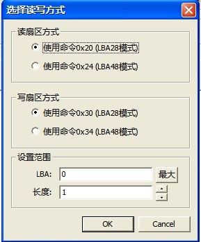
Figure 2.1-47(Way of Reading and Writing)
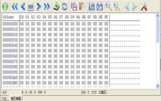
Figure 2.1-48(Sector Editing)
Users can edit the current sector, write into, save, search and other operations, and please refer to 2.1.2-1 (module list) for more information about the use of Hex Editor.
5. View S.M.A.R.T
Please refer to 《Conventional Common Module》 for more detailed information about “View S.M.A.R.T”.
7. View Report
“View Report” provides the function of displaying the current execution task, when users execute one task, users can check the operation result on the “View Report” options page. Users can terminate the task or save the task report.
8. View Working Directory
“View Working Directory” will display the current directory structure of task(as shown in figure 2.1-49).
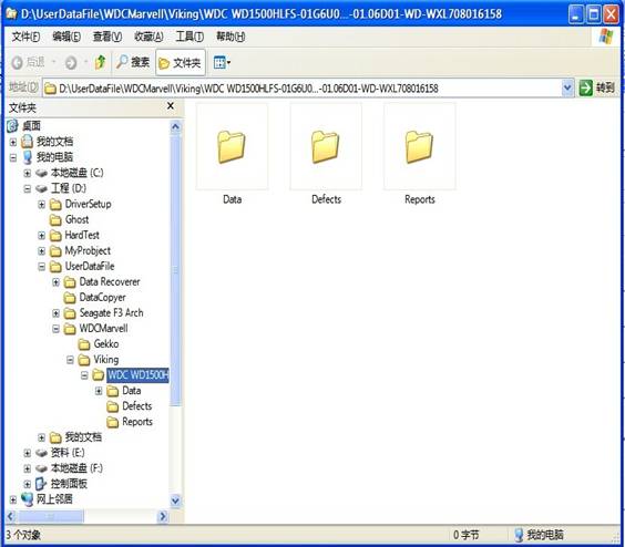
Figure 2.1-49 Working Directories
The default MRT Working Directory is D:\UserDataFile,please refer to 2.1.1-3(Save HDD Firmware Information) for more information about working directory.
2.2 Toolbar
The toolbar provides the shortcut of menu; please refer to “Menu and Main Function” introduction for more detailed information about each menu on toolbar.