Seagate Hard Disk Professional Tools
These documents are derived from MRT Firmware Laboratory.
For more information, please visit our website http://www.mrtexp.com
Content
1 Startup Interface
1.1 Connected to COM port………………………….………………………..2
1.2ATA Mode……………………………………………………………..……2
2 Menu Structure and Main Function
2.1 Diagnosis………………………………………………………………..4
2.2 Tools………………………………………………………………………..7
2.3 Terminal…………………………………………………………………..22
3 Toolbar
Startup Interface
1.1 Connected to COM Port
MRT Seagate module provides F3 series with hard disk maintenance functions.
When the Seagate HDD Professional Tools starts, it firstly asks user to connect to the COM port (Figure 1-1.1).
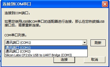
Figure 1.1-1(Connected to COM Port)
If users connect the USB to serial adapter, users can see the USB to serial adapter have already installed on the list: "Computer Manager - Device Manager - Ports (COM & LPT)". Users can also see "connected to COM port " from the drop-down list of dialog box, as shown in Figure 1-1.1 (Silicon Labs CP210x USB to UART Bridge (COM3)). When the users have already selected the COM port, just click "Connect" button to enter terminal mode; when users opens Seagate professional tools again, the program will automatically connect to COM port by default. For more information about the terminal mode, please refer to Terminal 2.3.
1.2 ATA Mode
If users do not connect the USB to serial adapter, or click the "Cancel" button in the "connected to COM port" dialog box, it will enter the ATA mode, and under ATA mode, MRT can communicate with HDD through SATA interface.
The program will read the Seagate hard disk module tables and CP object tables, and list basic information of HDD. "The physical sector size" indicates the current use of technology of HDD. If it is 512 Bytes which means that is the common hard disk, if it is 4096 Bytes, which means that the HDD is the latest HDD with 4KB technology.
The main interface
of Seagate professional tools is shown in Figure 1.2-1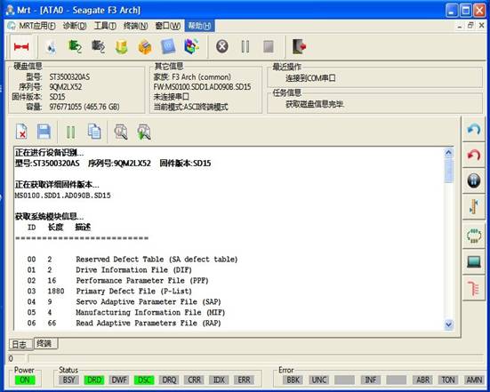
1.2-1(Main Interface)
Menu Structure and Main Functions
The main functions of Seagate Professional Tools mainly focuses on the three menus “Diagnosis”、“Tools”、“Terminal”.
2.1 Diagnosis
“Diagnosis”menu structure as shown in figure2.1-1.
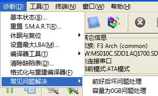
Figure 2.1-1( Diagnosis)
1. Basic Statue
2. "Basic statue" sub-menu is used to obtain the current basic information of hard disk, and the information is displayed in the form of the dialog box shown in Figure 2.1-2.
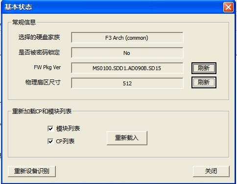
Figure 2.1-2(Basic Statue)
2 Reset S.M.A.R.T
"Reset SMART" sub-menu is used to re-initialize the SMART list. After users clicking the "Reset SMART", it will pop up the confirmation dialog box, as shown in Figure 2.1-3.
。
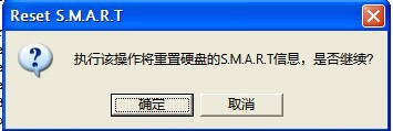
Figure e2.1-3(Reset S.M.A.R.T confirmation)
When users click "OK" button to perform this operation, the operating results will display in the log page.
3. Standby and Reset
About "Standby" and "Reset", please refer to “MRT Main Program Description”.
4 Set the maximum LBA
About "Set the maximum LBA", please refer to the “Conventional common Function Description”.
5. Translator tools
The menu "Translator Tools" has two submenus: "Translator regeneration" and "Translator recovery".
(1) Translator regeneration
"Rebuilding Translator" is used to re-establish the conversion table between the logical addresses and physical addresses, this operation may cause unpredictable results. Click "Translator Regeneration", it will pop up a confirmation dialog box, shown in Figure 2.1-4.
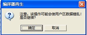
Figure 2.1-4(Translator Regeneration)
Users click "OK" button to carry out the operation, the operating result will display in the log page.
(2) Translator Recovery
6 Clear Defects Table
The function of “Clear defects table” is used to clear the Slide defects table (Slip List) and Alt defects table.
The first way of clearing is temporarily clear; it can be only modified in the HDD memory. The second is permanent, which will be written into HDD. The third is without clearing, but reloaded the defect table from the hard disk into memory.
"Clear defects table" is shown in Figure 2.1-5.
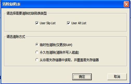
Figure 2.1-5(Clear Defects Table)
7. Formatting and Rebuilding Translator
"Formatting and Rebuilding Translator " (Figure 2.1-6), users can select the formatted area, formatting mode, and whether to clear the defects table as well as specify the maximum number of retries and so on.
After opening, the default option is translator regeneration, the common option is to select "Handle primary defects table". And then depending on the situation, you can select or not select "Handle growth defects table." Pay attention that make sure to check the "Disable user area format" when regenerating translator, otherwise the data of users will be formatted away.
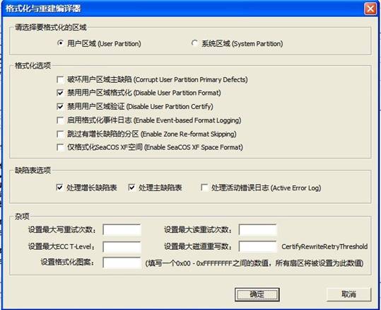
Figure e2.1-6(Formatting and Rebuilding Translator)
8. Solving common problems
“Solving common problems” aim at the common problems of Seagate hard disk: "the former after the bad", "capacity 0GB", it has made a one-key repair tools. To use this function, you must firstly enter the serial binary mode.
About the serial binary mode, please refer to "Terminal 2.3."
(1) Deal with the former after the bad
When the user enters the serial binary mode, click “Deal with the former after the bad ", the menu will appear the dialog as shown in Figure 2.1-7. When user clicks "Start Processing", MRT will start checking HDD failure, and the processing results will display in the log page.
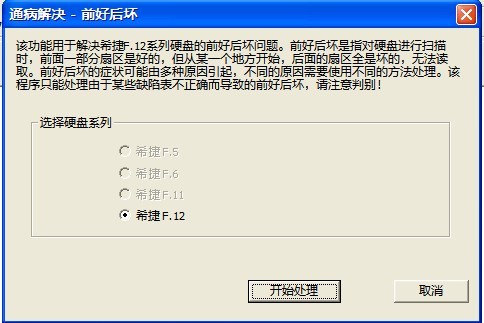
Figure 2.1-7(The former after the bad)
Firstly users set the appropriate Baud rate, and then enter the serial binary mode. After users click the "Start Processing", the program will automatically analyze HDD failures. If the failure is confirmed, the program will automatically repair it. After repairing, “the former after the bad” problem will be solved. If "Fail to confirm failure" is prompted, which means the problem of the hard disk caused by other reasons, then you will need to try another treatment way.
(2)Dealing with problem with 0capacity
As shown in figure2.1-8
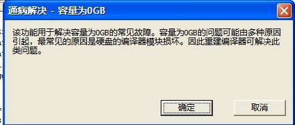
Figure 2.1-8(Capacity is 0)
2.2 Tools
"Tools" menu provides some basic operations on the hard disk, as shown in 2.2-1.
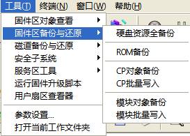
Figure 2.2-1(Tools)
1. View Firmware Area Object
“View Firmware Area Object” menu has three submenus: “Module Directory Table”、“CP Directory Table”、“HDD RAM”. The module list of Seagate contains the micro-program of Seagate, Address Translator and all kinds of data files. If these modules are damaged or break down, it will lead to the HDD failures and can't read data.
The list lists HDD module List, select the single module needs to be read, and then double-click; the program will read the module and open the module data in Hex Editor.
(1)Module Directory Table
“Module Directory Table”,as shown in figure 2.2-2
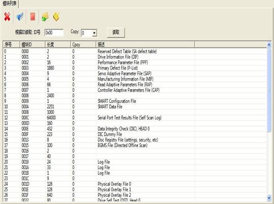
Figure 2.2-2(Module Directory Table)
(2)CP Directory Table
“CP Directory Table”, as shown in figure 2.2-3
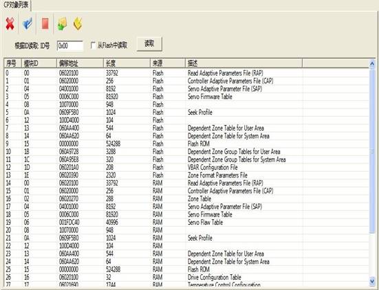
2.2-3(CP Directory Table)
(3)HDD RAM
“HDD RAM”, as shown in figure2.2-4
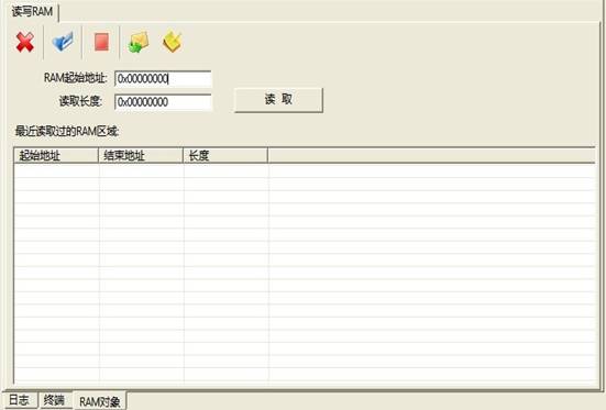
Figure 2.2-4(HDD RAM)
RAM starting list is blank. When user fills in the starting address of RAM and the read length, clicks "Read" button to read the specified RAM information. The RAM information after reading is displayed in hex editor, as shown in figure 2.2-5.
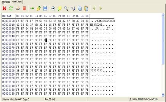
Figure 2.2-5
Hex Editor provides a common function with hexadecimal data editing. Here you can save a single module to a file. You can also load module data from the file and write it into HDD. The toolbar is located above the hex editor. When the mouse is moved to the “Toolbar” button, a message will prompt, indicating the button's function.
All of the toolbars in the program are in favor of this function.
2 Backup and Restore Firmware area
"Backup and Restore Firmware Area" menu is as shown in Figure 2.2-1.
(1)Full backup hard disk resources
The submenu "Hard resource full backup" provides all the resources to be backed up on the hard disk, as shown in figure 2.2-5, including "CP object", "module object", "ID Page List" and other hard disk resources.
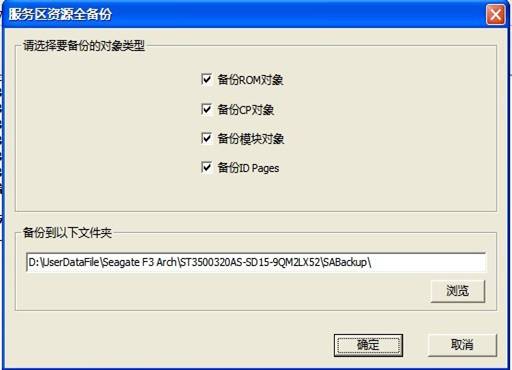
Figure 2.2-5(Full backup HDD Resource)
The user can select the backup option and the save path, then after setting backup option and click "OK" button begin to execute , the execution result will display in the log page.
(2) ROM backup
"ROM Backup" is as shown in Figure 2.2-6, namely backup HDD ROM information. Users can set the save path, after setting the save path, click "Save" button to save the current ROM information, and the save result will display in the log page.
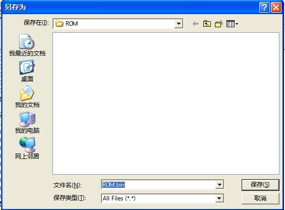
Figure 2.2-6(ROM Backup)
(3) CP object backup
"CP Object Backup" as shown in Figure 2.2-7, CP object is all the firmware information except HDD information. The user can select the CP object to be backed up as well as the path to save. The execution results will display in the log page.
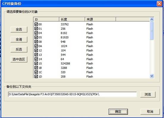
Figure 2.2-7(CP object backup )
(4) CP batch write
"CP batch write" means the specified CP object is written into HDD (as shown in figure 2.2-8). Please refer to the CP object on the "CP object backup." The user can choose CP module information needs to be written into according to their needs, after setting writing option and click "start writing" button to perform the operation of writing into. The operating result will display in the log page.
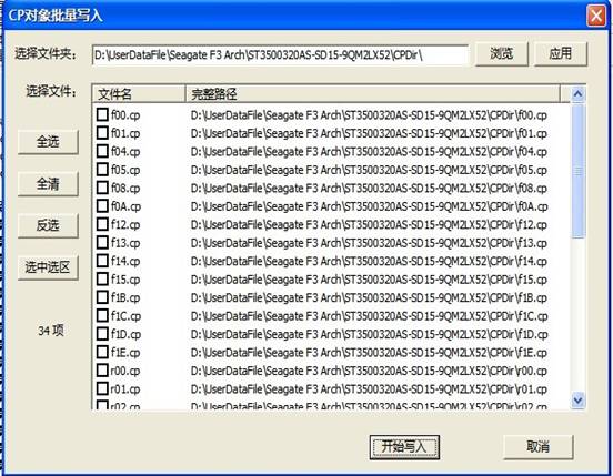
Figure 2.2-8(CP Batch Write)
5) Module object backup
"Module Object Backup" as shown in Figure 2.2-9, the module object is the information on HDD disk. The users can choose module object needs to be saved and the save path according to their own needs. After setting the backup options, click "OK" button to complete the operation. The execution result will display in the log page.
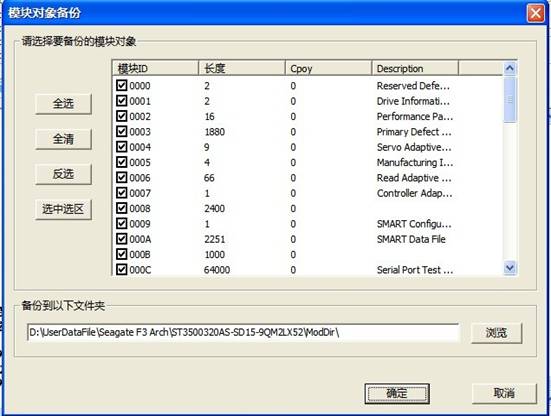
Figure 2.2-9(Module Object Backup)
(6) Module Batch Write
"Module batch write”, as shown in figure 2.2-10, users can write the backed up module into HDD. If user has backed up the module, the dialog box will display detailed information about the module. Otherwise it will display a blank page. Users can check and select the module to be written into and set up the modules needed to be written into. Then just click "Start Writing", the module information will be written into the hard disk. The written result will display in the log page.
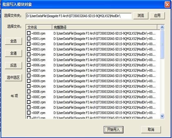
Figure 2.2-10(Module Batch Write)
3 Tracks Backup and Restore
"Tracks Backup and Restore" menu can be divided into three submenus "Read firmware according to the track "," Write into Firmware according to the track ", and "Track File Arranging Tools".
Tracks can be read in accordance with the logical address and physical address. It is generally recommended to use a logical address, which will not contain defects.
Senior reading tools allows users to input track number directly to read. Attention, like the format of 0x123456, which means that the track number is expressed in hexadecimal; and like the format of 123456, which means that the track number is expressed in decimal. The program can automatically identify hexadecimal or decimal format. If you want to use the 10 hex, then input the number value without adding the 0x prefix. Notice: If you use the physical address, there will be no distinctions between user area and system area. The front part of the physical track is the user area, after the completion of operation on user area, the system area track begin addressing.
The read tracks will be saved as. trk file , which can be modified with using such editors, like WinHex, and then write the file into HDD by using the track writing tools. Thus it provides a way to repair the hard disk.
(1) Read firmware by track
"Read firmware by track", this function needs to enter the serial binary mode. After setting the transmission mode, click “Read firmware by track”, it will pop up the "New Folder" dialog box as shown in Figure 2.2-11, the user can set the save path of information that has already read, and add descriptive information providing convenience for the next view.
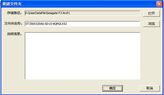
Figure e2.2-11(Newly-built Folder)
Click "OK" button to complete the setting. Simultaneously it displays the read information of track, the selection option display the result of reading track , as shown in figure 2.2-12.
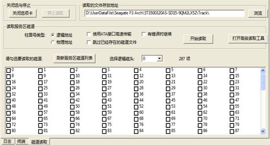
2.2-12(Read Firmware by Track)
(2) Write into Firmware by Track
"Write into Firmware by Track”, as shown in figure 2.2-1, that is to say, firmware information which has been stored is written into HDD, and click "Apply" button to refresh the file list. File List lists the track files has been saved in the working directory, check the track file to be written into, and then click to start writing. These track files will be written into HDD. The file name of the track file will specify which track to be written into. If you want to write into the specified head, you should check the "Write into the specified head" and fill in an effective head number. After checking "to continue after an error," even in the face of bad sectors, it will continue to be written into. Sometimes this way can be used to repair the track UNC errors.
When writing into tracks, there are 3 kinds of transmission modes. If the ATA interface of hard drive can work, it is recommended to use "ATA high-speed transmission", which would be the fastest. Otherwise, it can only use pure serial transmission. By setting a higher baud rate, it can improve the speed of serial transmission.
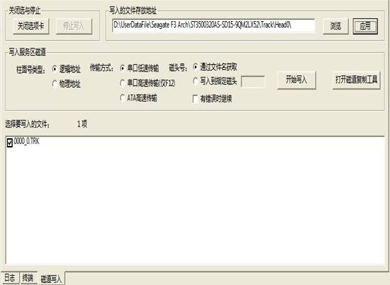
Figure 2.2-13(Writing into Firmware by Track)
Attention: it contains certain risks of directly writing into track service area. Before operating this, please make sure you have full understanding of distributions and functions of these tracks.
(3) Track File Arranging Tools
" Track File Arranging Tools " , as shown in Figure 2.2-14, is used to collate track file that have been read out, the arranging content contains the useless information such as invalid tracks or empty contents.
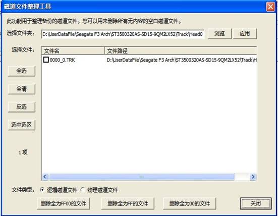
Figure 2.2-14(Track File Arranging Tools)
4 Security Subsystems
For more information about the "security subsystem", please refer to “Conventional Common Function Description”.
5. Service Area Tools
“Service Area Tools”menu structure as shown in figure 2.2-15.
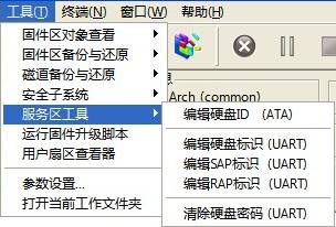
Figure 2.2-15(Service Area Tools)
(1) Edit HDD ID
"Edit HDD ID" is used to set up and save hard disk ID information, including hard disk capacity, as well as other additional information. When the user resets the new current hard disk capacity, in Seagate professional tools information bar, it cannot display the updated capacity information immediately. It requires the user to exit from the program and turn off the power to re-enter. At this moment, the updated information is displayed in the status bar. Or the user can open the "basic status" dialog box (on the "basic state", refer to 2.1 "diagnosis - the basic statue"), click "re-identification of equipment" button to update the current hard disk information.
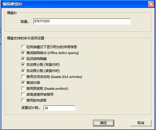
Figure 2.2-16(Edit HDD ID)
(2) Edit HDD Identification
"Edit HDD Identification" as shown in figure 2.2-17, this function needs to enter the serial binary mode (about serial binary mode, refer to 2.3"Terminal - serial binary mode"). When the user enters the serial binary mode, the hard disk logo can be modified. As HDD Identification hides in multiple places, and therefore the user needs to modify multiple places and the modified multiple results are invisible.
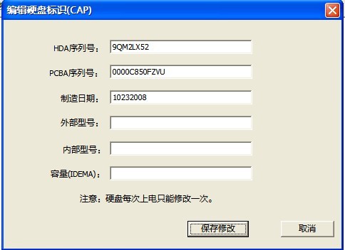
Figure 2.2-17(Edit HDD Identification)
(3) Edit SAP ID
"Editing SAP ID" as shown in figure 2.2-18, this function needs to enter the serial binary mode, used to modify the primary serial number of HDD. The modification result can be in the information bar.
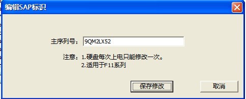
Figure2.2-18(Edit SAP ID)
(4) Edit RAP ID
"Edit RAP ID" as shown in Figure 2.2-19,
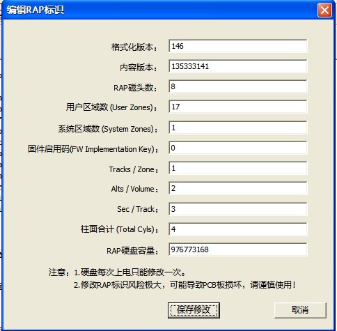
Figure2.2-19(Edit RAP ID)
(5)Clear HDD password
"Clear HDD Password", as shown in Figure 2.2-20, this function needs to analyze HDD password under serial binary mode.
First you need to set a higher baud rate, and then enter the serial binary mode, the analysis result will display in the log page. After the completion of analysis, passwords will be erased, including the main password and user password. When passwords are successfully cleared, user data can be read normally.
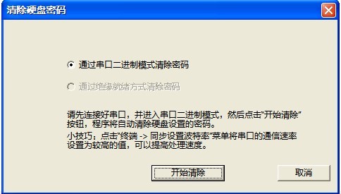
Figure 2.2-20(Clear HDD Password)
6 Run the firmware upgraded script
Seagate firmware upgraded script is the upgrade script to HDD firmware by Seagate Company. This file contains a plurality of segments, each segment executes a relatively independent function; some segments may be used alone; or a plurality of segments can be combined together to perform a complete function. This function can create multiple segments and also can merge multiple segments, as shown in Figure 2.2-21.
Attention: this function only supports SD1A series firmware temporary.
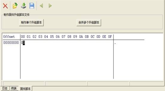
Figure 2.2-21Firmware Upgrade Script
“Running the firmware upgraded script” is used to perform upgrade script of Seagate firmware; this kind of script can perform some operations, and update HDD firmware area. In the folder of "data \ Seagate firmware upgrade scripts" inside MRT installation package, we provide some parts of standardized firmware upgrade script of Seagate. For some malfunction, you can try to write directly into the corresponding firmware upgrade scripts, and then in this way, they can be repaired.
After opening the firmware upgrade script, Click![]() “Open File” button to
load Seagate Firmware Upgrade Script, users can select to modify the script,
and the click
“Open File” button to
load Seagate Firmware Upgrade Script, users can select to modify the script,
and the click ![]() “Write into” button to
write firmware into HDD.
“Write into” button to
write firmware into HDD.
7 Users Sector Viewer
User sector viewer can quickly and easily view the user sectors. When entering the serial binary mode, it will use the terminal serial to read user’s’ data. Under the common mode, you can use the ATA to read user’s data. When ATA is not ready, you can try to use the serial port to read user’s data. At first, you should set an appropriate baud rate, and enter the serial binary mode.
In the dialog box of reading new sector, it is necessary to input the LBA address and length. If you enter the serial binary mode, the following options will start. If the ATA can work, it can improve the speed when checking the "Serial and ATA hybrid transmission”. When the address translator fails, checking the "When logical LBA read fails, and try to use a physical address", you can read the maximize data. Generally speaking, this can read hard disks including “HDD with the former after the bad”.
2.3 Terminal
The menu structure of "Terminal" is as shown in Figure 2.3-1.
The function of reading by using Serial terminal user data can be extended to DR. It only needs to select the factory program to read in DR and enter the serial mode in the Seagate factory program. This can copy and mirror user data in the serial, even if HDD ATA interface can’t work. About this function, please refer to the description “data recovery functions” instructions.
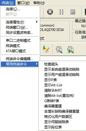
Figure 2.3-1(Terminal)
1 Connect
"Connect" is connecting to COM connection of hard disk. Only when a user connects a "USB to serial adapter", we can use this function. About the COM port, please refer to "1.1 connects COM port".
After connecting the COM port, the user can enter terminal mode (Figure 2.3-2). In terminal mode, you just need press "ctrl + Z" to enter the terminal command, and press "ctrl + T" into the ATA terminal mode. Users can view the current transmission mode in other information bar of the information bars.
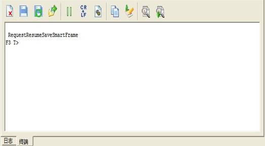
Figure 2.3-2(Terminal)
2 Disconnect
"Disconnect" is to disconnect the COM port which has been connected, after that it will enter the ATA transmission mode.
3 Connection Attribute
The menu "Connection Attribute" can be divided into two submenus: "Port Settings" and "Timeout settings".
"Port Settings" is set for transmission port (as shown in figure 2.3-3), including the baud rate selects (only set the host baud rate; if the host baud rate is inconsistent with the hard disk, it will cause an error.), check whether there is the odd or even number, data bits number, stop bits number and whether there is data flow control.
"Timeout settings" is to limit the reading time of hard disk (as shown in figure 2.3-4).
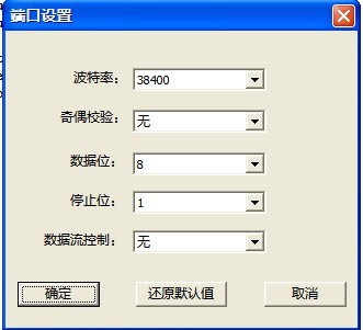
2.3-3(Port Setting)
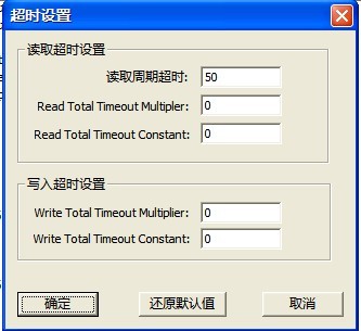
2.2-4(Timeout Setting)
4 Set the synchronized baud rate
"Set the synchronized baud rate," as shown in Figure 2.2-5, firstly user should set the baud rate of HDD port to the specified value, and then set the synchronous host port baud rate, in which the baud rate of the hard disk and the host baud rate is consistent with each other.
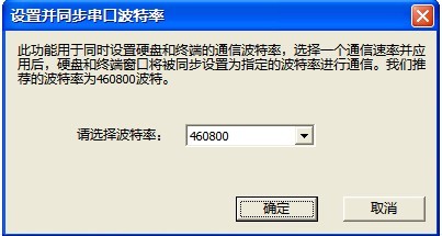
2.2-5(Set the synchronized baud rate)
5 Serial binary mode
When the hard disk has already entered the "Serial binary mode", it will set up the timeout of reading and timeout of writing to an appropriate number value to be suitable for the mode. Please do not perform the functions under ATA mode after "entering the serial binary mode", which will cause the program can’t work normally, and some functions of the program must operate under this mode. Timeout settings will be restored after exiting the program, and then it will enter the terminal mode.
6 Terminal mode
"Terminal mode" is used to convert another kind of mode into terminal mode. About "Terminal Mode", please refer to terminal 2.3.
7 ATA interface mode
"ATA interface mode" is to transform the transmission mode into "ATA mode." For more information about "ATA Interface", please refer to “MRT Hardware Description and Installation Instructions”.
8 Terminal Commands Edit
"Terminal Commands Edit," as shown in figure 2.3-6, it provides a common terminal commands with modification, deleting and user-defined commands.
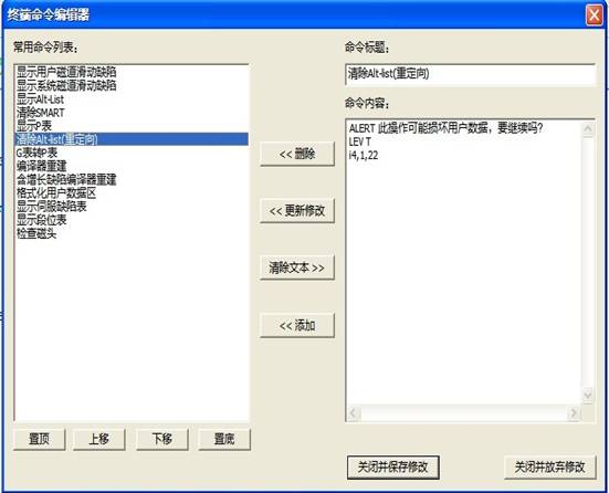
Figure 2.3-6(Terminal Commands Edit)
Users can self-set the arrangement of the common used command list, users select one piece of command , click “Top” button, this command in the command list will be placed in the top, click ”Up” button, it will move up one line, click “Down” button , it will move down on line. Click “Bottom”, it will move to the last line.
When users need to delete one command, they need to use left-click to click command line needs to deleted in the list of the commonly- used commands, click "Delete" button to delete the command; When users need to modify one command, they need to use left-click to select the command needs to be modified in the "Commonly-used Commands list". At this time, users can modify the command title in the command title, and modify the command you want to send in the contents of command. After modifying, then click "Update Modification" you can update the commands that has already modified to the commonly-used command list: when users need to add one command, firstly they need to click "Clear text" button, then it will clear out the two texts of "Command Headline" and "Command Contents", and then users can add commands, the keyword " ALERT " indicates that this operation may damage the hard disk, the dialog box will pop up when you perform this operation, the prompt content is text message after space; the keyword " LEV " represent the subsequent character as the command level. Some commands can be performed in the specific level. After setting the prompt message and the command level, users can input the command code. After users setting the command, click "Add" button to add this command to the list of commonly- used commands.
If users want to save the settings after performing each step, users must click "Close and save modifications" button, it can be effective, and otherwise the modifications will be invalid.
The modified commands are commonly- used in the terminal command menu, when users want to send this command later, just click the name of the command directly.
9 Common terminal commands list
"Common terminal commands list" provides shortcuts of commonly -used terminal commands. There are 13 commonly-used commands by default (as shown in figure 2.3-1), the user can modify through “Terminal Command Editing".
Toolbar
The toolbar provides shortcuts of menu items. About specific functions of toolbar buttons, please refer to “Menu Structure and Functions”.