MRT Western Digital Professional Repair Tools Instruction
These documents are derived from MRT Firmware Laboratory. For more information, please visit our website http://www.mrtexp.com
Content
1. Startup Interface
1.1 Select HDD Mode Dialog Box……………………………………………………………..2
2. Menu and Main Function
2.1 Diagnostics menu………………………………………………………………………….7
2.1.1 View Basic Information…………………………………………………………….7
2.1.2 Service Area Operation…………………………………………………………….8
1. Full Backup Resource………………………………………………………….9
2. ROM Operation…………………………………………………………….10
3. RAM Operation…………………………………………………………….14
4. Module Object Operation……………………………………….15
5. Track Object Operation…………………………………………………….18
6. Edit ID……………………………………………………………….21
7. Repair Slow Start………………………………………………………..21
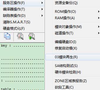
8. 03 Module Regeneration…………………………………………….22
9. SA Menu Structure Test …………………………………………………….23
10. Module Hardware Test…………………………………………………….23
11. ZONE Table Report(View ZONE Table Information)………….24
2.1.3 Translator Operation………………………………………………….25
2.1.4 Defects Table Operation…………………………………………………26
1. Defects Table Report……………………………………………….26
2. Edit Defects Table…………………………………………27
3.Clear Defects Table………………………………………….27
4. G_List to P_List…………………………………………………….27
5. Generate P-list from self-calibrate………………28
2.1.5 Clear S.M.A.R.T.………………………………………………………….28
2.1.6 Formattng HDD…………………………………………..28
2.2 Service Area Operation………………………………………………………….30
2.2.1 Module Lst………………………………………………………………….30
2.2.2 Head Test………………………………………………………………….30
2.2.3 View and Reset Password Information of HDD…………………………….31
2.3 Tool ……………………………………………………………………………….32
2.3.1 Estimated area Object Viewer………………………………………….32
1.Module List…………………………………………………………….33
2.HDD Resourece Viewer…………………………………………………….36
3. Search Module List from SA…………………………………………….42
2.3.2 Way of Reading and Writing………………………………………………….42
2.3.3 Self- calibration Test………………………………………………….42
1. Editing Items…………………………………………………………….44
2. Set to current page………………………………………………………….43
3. Refreash List…………………………………………………………….43
4. Write Into HDD…………………………………………………………….43
5. Open the self-calibration……………………………………….43
2.3.4 User Sector Viewer………………………………………….44
2.3.5Logical Scanning…………………………………………………………………45
2.3.6 CHS Defects Table Editor……………………………………………………….47
2.3.7 LBA Defects Table Editor……………………………………………………….50
2.3.8 Sleep and Reset………………………………………………………….52
2.3.9 Open Working Directory………………………………………………………….53
2.3.10 Parameter Setting………………………………………………………………….53
Startup Interface
1.1 Select HDD Mode Dialog Box…
Select HDD Mode Dialog Box,as shown in figure 1.1-1
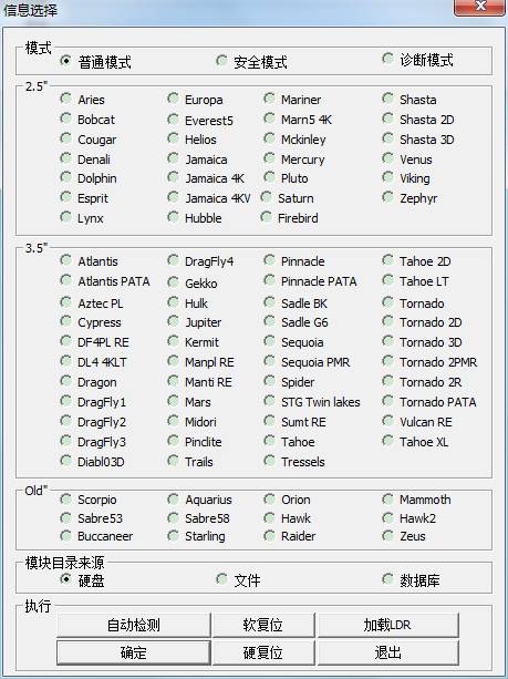
Figure1.1-1Mode Selection
The dialog box lists models and modes of program startup(the default startup mode is the common mode) supported by Western Digital(namely WD). Users can manually select the model or automatically detect, after selecting the mode, click “Startup” button to enter the interface of WD Professional Tool.
“Common Mode” is used for HDD to normally visit and each module can be normally opened .
If in “common mode ”, HDD can’t be normally ready or can't read the information of ROM, RAM and other models, users can select “Kernel Mode”or "Diagnostic Mode" according to practical situation. In the two modes, the program will carry on the special treatment on HDD; the program enhanced the processing capacity of HDD failures.
In some circumstances, the program can't normally acquire HDD SPI information and so on, at this time it will pop up a dialog box (As shown in figure 1.1-2). The program below the figure will calculate a default SPI and then fill it in the editor box based on having gained other data. In general, users don’t need to modify it.
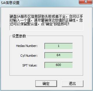
Figure1.1-2Input SA SPT
When HDD disks of “Safe Mode ” stops turning, users can only visit the module information on PCB Board, namely to say that can only visit ROM information and can't visit the content of HDD disks so as to achieve the purpose of avoiding change the disk content.
“Diagnostic Mode”is MRT Firmware Laboratory to develop the repair function for WD Series HDD, when HDD can’t be normally ready, users need to manually “short circuit” HDD Safe Jumper. Then when the program boots, select “Diagnostic Mode”, click “Automatic acquisition model”or manually select the mode, after starting the program , users are required to set up working folder to save mode information(as shown in figure 1.1-3 ) so as to restore initial statue of HDD when errors occur. The dialog box lists models and modes of program startup(the default startup mode is the common mode) supported by Western Digital(namely WD). Users can manually select the mode or automatically detect, after selecting the model, click “Startup” button to enter the main interface of WD Professional Tool.
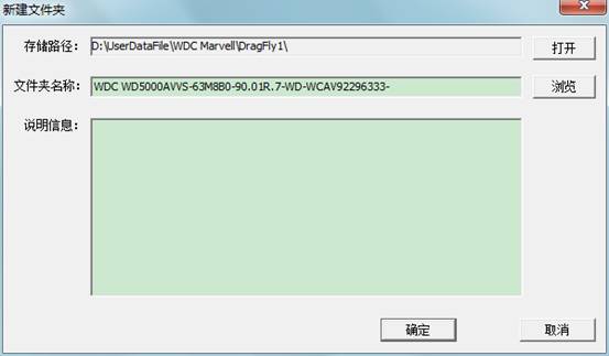
Figure 1.1-3 Set up working folder
These different startup modes will demonstrate in the supporting instruction for use of video tutorial.
Main Interface
The Main Interface of WD Professional Repair Tools, all the operations by users will be recorded in log page. As shown in figure 2.0 – 1.
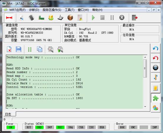
2.1 – 1(WD Module Main Interface)
The design of the main interface is mostly similar to UDMA to meet the majority of users’ habits. In “HDD Information”, it is very convenient for users to view the model of HDD, Series Number, capacity and Firmware Version Information. “Other Information” also contains the abundant information, for example as you view, it not only contains “Family Information”, but also the “Track, Head, SPI” of SA area, there are still ROM version and Startup Mode information. The right side of toolbar contains the shortcuts of “Soft Reset”, “Hard Reset”, “Sleep”, “Wake Up”, “Calibration”, " ABA approach read and write HDD "" ID read and write””track read and write” and other functions from the top to the bottom. Through our well-designed, all these provide the convenience and flexibility of operation for users.
Menu and Main Functions
WD Professional Tool Function is mainly concentrate on the "Diagnostics", "Service Area Operations", "Tools” three menus; each menu structure is as follows:
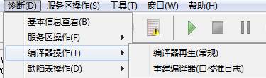
2.1 Diagnosis
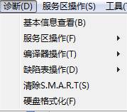 2.1 – 0(Diagnosis Menu)
Its submenu item sequence as shown in figure 2.1.1 – 1, we will explain one by one.
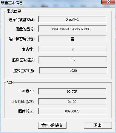
2.1.1View Basic Information
“HDD Information”submenu can display the current basic HDD information in the form of the dialog box, and it can detect HDD again. As shown in figure 2.1-1.
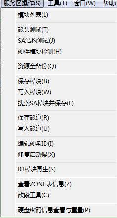
2.1.2 Service Area Operation
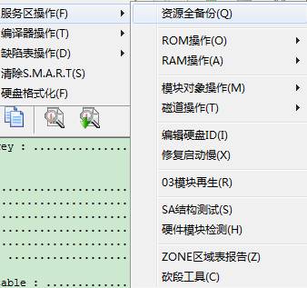
2.1 - 2
For the
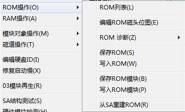
convenient use for users, we remove ROM Operation in the sub-menu item of SA
menu, integrate RAM Operation and single it out as a top-level menu. As shown
below: 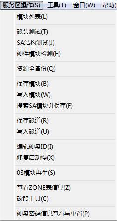
2.1 - 3
Although we
don’t extract ROM, RAM, they can be easily searched in the main interface. 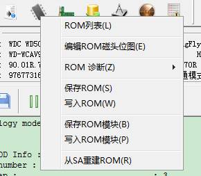
2.1 - 4
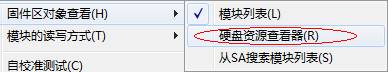
Use the mouse to click that icon represents “Chip”, ROM-related operations will come out, RAM operating is on its side.
Below we take the figure2.1-1 for example, explain one by one from the top to the bottom.
1. Full Backup Resource
2.
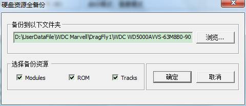
.Obviously, this function will backup the entire resource of HDD, including Module, Track as well as ROM.
① ROM List
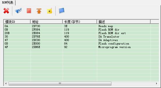
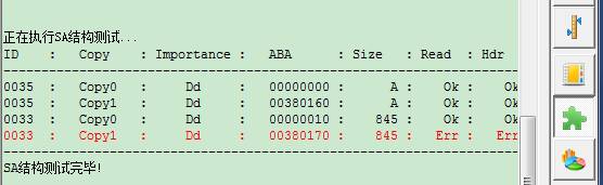
The toolbar above from the left to the right is: "Close Tab", "View the selected Module ", "Stop Task" "Turn to the first row" "Turn to log page" "SA structure detection”.
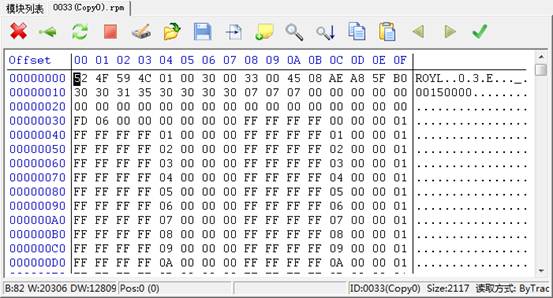
Double-click Module Item, or click to view the selected module, it will jump into HEX Page (16 Hex Editor Page).
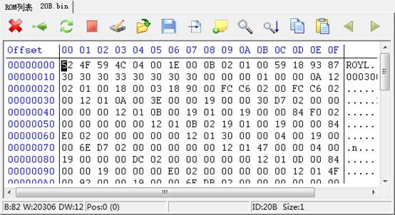
As shown, the figure displays 20B module, on the Hex Page, it can view modify, write into, calibrate, seek , carry on filling characters in the specified area, copy, paste, save it as the file or open the backup file and other operation to the data of module. If the data of module is wrong, it is very convenient for us to edit it. Similarly, when we talk about the common module list later, at the same it will jump to this interface, but data displayed is the module that we clicked.
② Edit Head Bitmap
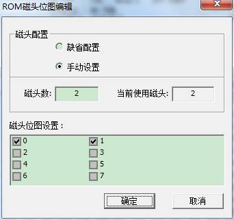
The operation is simple, if we detect one head breaks down, we don’t need to start the head, so we can tick it off here, then click “OK”. Above is the option “Default Configuration”, we will change the switch of head bitmap if we select the option, and then we are not allowed to edit head bitmap, HDD itself will choose the non-default head bitmap to use.
③ Diagnosis ROM
The menu contains two kinds of functions, one is ROM data detection module, and the other is the overall ROM data detection. At the present, it only supports ROM data detection module.
④ Save ROM
Obviously,it will save the entire ROM,users themselves can choose where to save.
⑤ Write into ROM.
The file is selected by users to write into ROM, and then click “OK.”
⑥ Save ROM Module
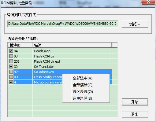
It is for us to select the backup path, and we can check any module need to be backed up in the checkbox, and we can see the program still provides the right-click menu, which it is very convenient for us to select. Click “Start” button to begin to backup.
⑦Write into ROM Module
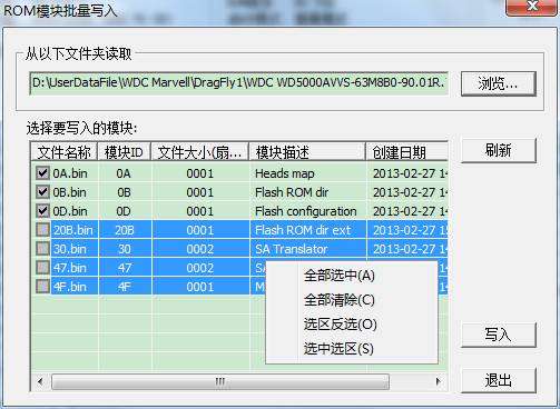
You can see the interface similar to interface of saving ROM interface. Click “Browse” to select rom module folder backed up just now, the list box will appear the information of module that has already been backed up. Check any file that we need to write into, click “Write into” to begin the task.
⑧Rebuild ROM from SA.
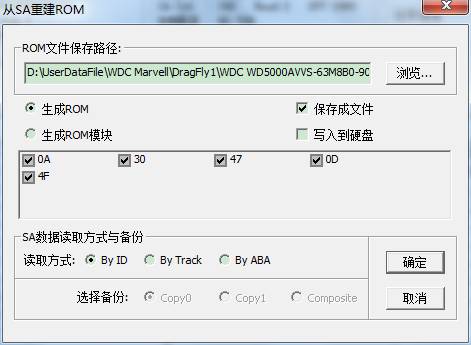
There is no doubt that the function of “Rebuild ROM from SA” in MRT is very powerful. From the figure, we can see that we firstly need to select the path of file needs to be saved. If check “Save the File” button, the program will save both the source file and the newly-built file to the selecting file during the course of generating ROM. Since this function extract from module data of SA service area, through the algorithm and merger to generate the new file, so if SA data is wrong, it will lead to the new generation of data is also incorrect. Thus, it will strictly detect SA module data in the process of generation, so under some circumstances, it will generate the log report with red words during the course of generating the new file. As shown below:
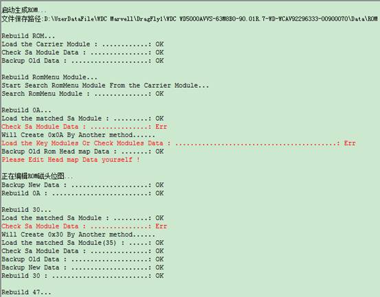
Here can only list one part of log because of the problem of inadequate interface. If here appears red words, please take it easy and observe the log above, we can see there are significantly separated when generate different kind of modules. For example the figure above:“Rebuild 30。。。”to“Rebuild 30 : …………: OK”is the information of generating 30 modules. Red words in the middle of figure are to detect the incorrect related data in the process of generating 30 modules, so the next sentence translated into Chinese is “it will take another way to generate 30 modules.”Finally, we can see the second way to generate 30 modules turns out a success.
Now we can draw a conclusion, to ensure the success of generating ROM, the program will firstly use one way to generate during the course of generating each module. If the first way to generate is unsuccessfully or detect the incorrect generating data, then it will start the second way continue to generate.
3. RAM operation
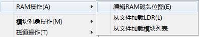
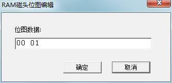
① Edit RAM Head Bitmap
② Load LDR
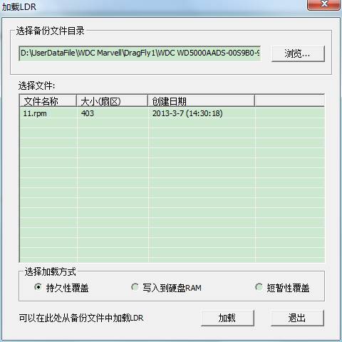
If the folder selected to backup modules exists 11.rpm, 13.rpm and other documents,they will be listed in the list, there are three kinds of loading modes geberally11 to choose the first way, 13 to choose the second way. Click “Load” button to begin to load.
③ The way of operation is the same with loading LDR.
Operation way is same as loading LDR.
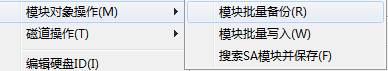
①Batch Backup Module
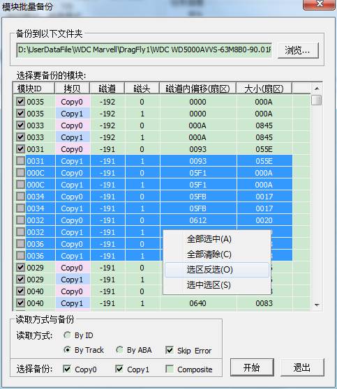
The same to save ROM module mentioned before, it is decided by us to select the backup path and we can select any modules need to be saved, provides the right-click menu to make operation conveniently. The difference is that we can also choose the way of reading data from HDD as well as the backup content, Copy0,Copy1,or Composition method.
②Module Batch Write
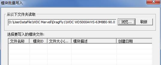
As shown above,it will appear this interface when you click “Function” button, and then the list box doesn’t display any file. We need to select the folder with module, click “Browse” button; it will appear the Select Folder Dialog Box:
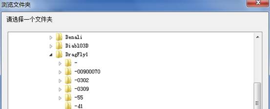
When we have selected the file path that has already been backed up, there is content in the list box:
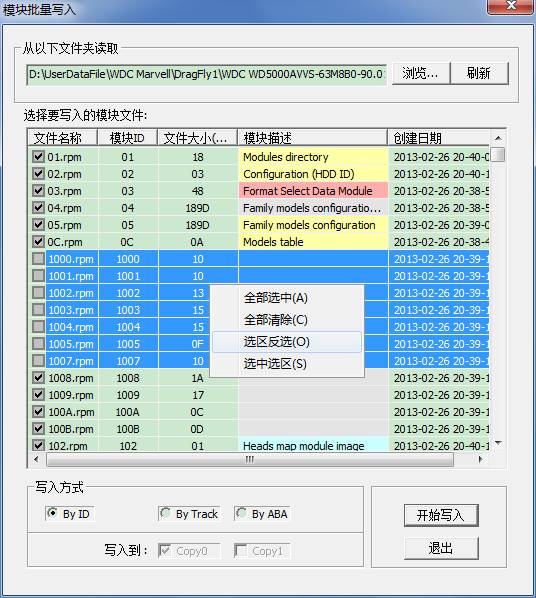
At this moment,we can select any files need to written into and use what kind of way to write into HDD, when you choose to use by track or by ABA to write into, please pay attention to which backup needs to be written into.
③Search SA Module and Save it
This function is one of the most characteristic function among MRT Western Digital Professional Repair Tool, open this function, it will appear the following interface:
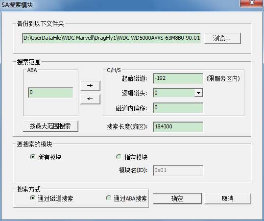
This dialog box looks like complex but it is simple. We look down from the top:
1) After selecting the research to module, save the file as the folder path.
2) Search Range:1. The starting address of searching(We know there are two way to express address, in fact this also provides one useful tool: the switch between ABA address and CHS address. When we click “OK” button to search, please click “Switch” button to make sure the consistency between ABA address and CHS address. Of course, the program will remind us)2. Search the length.
3) Modules need to be searched, “All the modules” and “Specified modules”,when we select the specified modules, we can also input name of modules, pay attention , it is 16 Hex Editor.
4) Search method,why we need to fill in ABA address and CHS address, in fact it can provide two way of searching here.
How about, it is quietly simple, isn’t it? ^_^
![]()
①Track batch backup
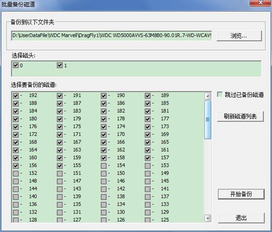
Do you see it, here also reflects one feature of MRT, when it pops up on the screen, we will by default for you to check track with module data and ignore such track with no content of module data, and save your valuable time. The interface is simple; you know how to use at the first sight.
②Write into Track
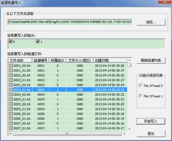
The same as writing into module firstly select the file path with the track, the list box lists track file list, check track files need to be written into and check these files to be written into which heads, and then begin to write into. Attention, after the completion of selection, their meaning is to write files checked by you into the head checked by you!Therefore,if we want to restore the original backup, we need firstly to check file with number 0 header, and then check 0 head (only write into number0 head)!Open this function after the completion of writing into, and check the 1st header files, check the 1st head, just write into the 1st head!Like this, it can restore your original backup of track file.
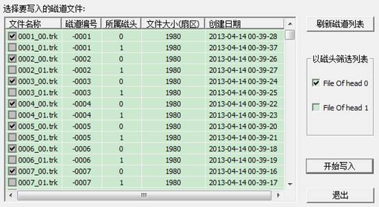
For convenience, we set up two check buttons on the side, check“File On head 0”,number 0 header in the list box will be checked!Effect is as follows:
Menu Position:
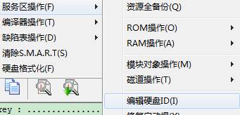
Open the Interface:
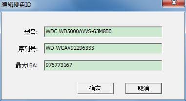
As shown in figure, you can directly edit three attributes of “Model”“Series Number”“Maximum LBA”in the edit box. After modifying“Maximum LBA”,power-off, Re-identification Device, you will see the change of capacity displayed on HDD!
Menu Position:Located below the editing ID
Open the interface:
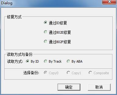
As shown in figure,there are three ways to repair, and then select the way of reading data to carry on repairing.
Menu Position:
Open the interface:
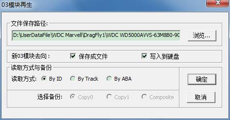
As shown in figure,select save path, whether to write into HDD, Or whether to save it as file, and then select the way of reading data, it can begin to work.
Menu Position:
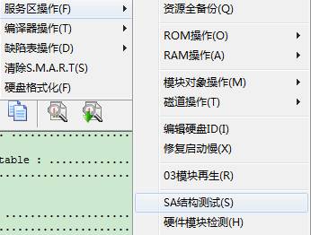
There is no interface after clicking “Function” button, directly turn to log page to view and detect the detailed information.
Click “Data Read Mode” on the right side, you can select different kind of “Data Read Mode” to carry on detecting module data test.
Attention:Data Read Mode on the right side of HDD can only control module list page, Hexpage page and module list page in Resource Viewer.
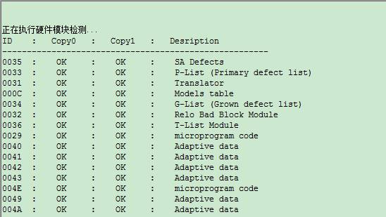
The same as SA structure test, click “Menu”, it will instantly begin to work, you can see the detailed detection information in the log page.
11. ZONE Report Table(view ZONE table information)
Menu Position:
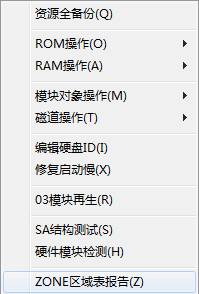
Click “Menu” button, it will appear the detailed information about ZONE table on the log page.
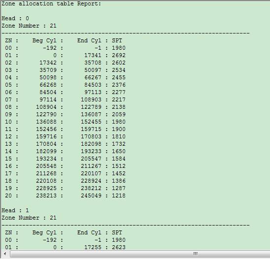
It can be seen that the information displayed differently above is according to different heads.
2.1.3 Translator Operation
In the menu you can see there are two kinds of functions, both of them are used for translator regenerate. One is to rebuild translator from calibration log; the other is to rebuild translator according to routine way. Click “Menu” button, it will appear the related information on the log page; wait for the completion of operation.
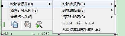
2.1.4 Defect Table Operation
Menu Position:
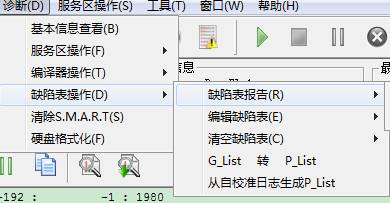
We still explain from the top to the bottom:
![]()
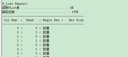
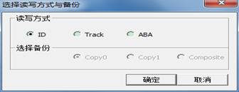
Click “P-List report,or G-List report”,it will pop up a dialog box and let you select what way to carry on reading module defect table, as shown in figure blow:
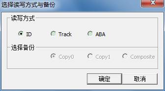
So the log page will appear defect table- related information, its print format as follows:
![]()
The sane with defect report table, it will also pop up reading and writing confirmation dialog box. Specific figure is not listed.
After the confirmation of reading mode, it will open one page on the “Defect Editor”:“P-List”,as shown in figure below:
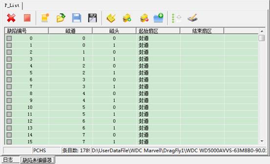
When open this page, the program will read out data in P-List or G-List, and save it as the file, one is the original file backup, the other is the processed“*.chs” format file. Opened on this interface is the chs format file. The specific mode of editing can be seen in detail on the “CHS Defect Table Editor”.
The path of backup file can be viewed in the logo page:
![]()
![]()
This function is very simple, after selecting the Data Read Mode; it will read module data, retain module head, empty defect table and write back data.
Perform this function,it will enter G to P operation, after the completion of switching, empty G-list.
As shown in figure above, click “Menu” button to begin to work. Turning to log page to view the detailed information, just wait for the completion of operation.
2.1.5 Clear S.M.A.R.T.
Menu Position:
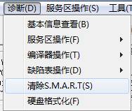
Open the interface:
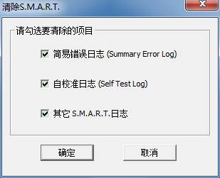
You can check the log need to be removed, click “OK” button to begin to work. The log page will list the statue of clearing work, just wait for the completion.
2.1.6 HDD Formatting
Menu Position:
Open the interface:
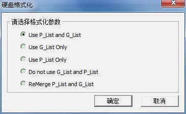
As shown in figure above,select the formatting parameters and then click “OK” to complete.
Parameter Introduction:
1) Use P-list and G-list
2) Only use G-list
3) Only use P-list
4) Don’t use G-list and P-list
5) Combine P-list and G-list
2.2 Service Area Operation
If you firstly look the diagnostic menu, so you can observe most of functions of menu items here is the same with diagnostic menu. Since the diagnostic menu has much class, this may cause too much inconvenience for users; based on this situation, here we extract some commonly used functions, and place here to make a shortcut for your convenience.
If we watch carefully, we can find that there are some items of function not existing in diagnostic menu, next we will give a brief introduction about function not mentioned before from the top to the bottom.
2.2.1 Module List
The module list here is also a shortcut access from “Tool –> Firmware area Object Viewer
–> Module List” function. The specific introduction will be introduced in “Tool.”
2.2.2 Head Test
Menu Position:
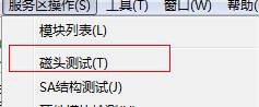
Open the interface:
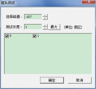
In this function, track value filled in by default is calculated by users through different HDD, to ensure the track needed to be tested has no data, it is a suggestion that don’t arbitrarily change if there are no errors reminded by the program, to avoid the loss of SA data in the process of testing.
The maximum length of the test will not exceed SPT value of service area track.
2.2.3 View and Reset HDD Password Information
Click “Menu” button, it will appear the dialog box of selecting data read mode, after confirmation of reading and writing mode, it will appear the following interface:
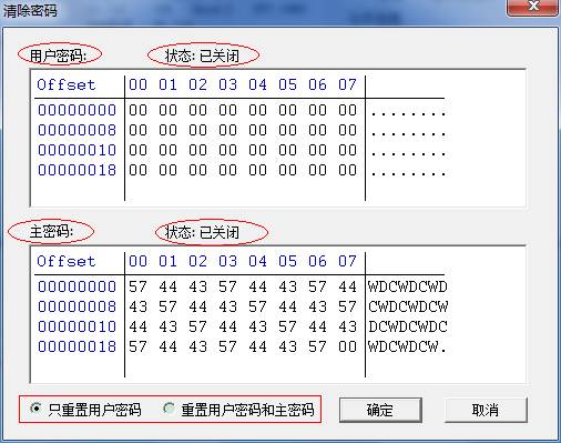
As shown in figure above, the interface can not only display the content of password, but also the statue of password.
The radio button in the bottom left Conner with the red frame can be selected as goal to be cleared, click “OK” button to complete.
2.3 Tool
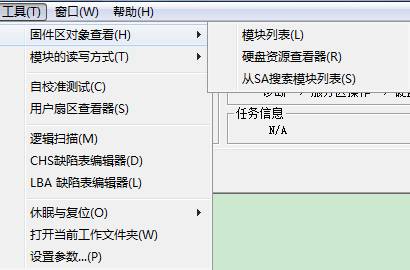
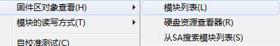
2.3.1 Estimated Area Object View
Menu Position:
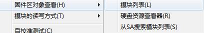
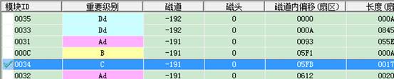
After clicking the function, it will list module list, users can view the information of module through module list, for example ID, ABA address, belonging to which track, track inside deviation and so on.
Click the three buttons on the right side box to make list display the different information.
![]() :Click this button to directly
turn to the first line.
:Click this button to directly
turn to the first line.
![]() :Click this button to turn to
the log page.
:Click this button to turn to
the log page.
![]() : This button indicates that
make test on hardware to the selected items, it will tick in front if the test
turns out a success:
: This button indicates that
make test on hardware to the selected items, it will tick in front if the test
turns out a success:
![]() :This button indicates that make
test on SA structure to the selected items. After clicking, the later three
items behind list items will fill up:
:This button indicates that make
test on SA structure to the selected items. After clicking, the later three
items behind list items will fill up:

Double-click items to jump to Hex Page to view data:
In the HexPage Editor,the operation is mostly similar to other MRT professional tools. The difference only lies in different pictures in some individual toolbar. The last point is that the last function is different from other modules, it is uniquely owned by WD: Module Verification.
![]() :Click this function, it will
display the following menu :
:Click this function, it will
display the following menu :
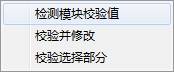
1.Detection module checksum 2. Check and modify 3. Check selected part
Tips:when open OA module in ROM list, it will be more of a menu: “Check Head Bitmap” .
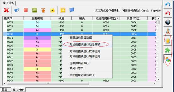
Right-click list, it will appear the right-click menu:
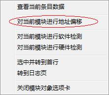
Right-click menu has one option, which can carry on “module address offset” to the selected item. Click “Menu” button, it will appear the following interface:
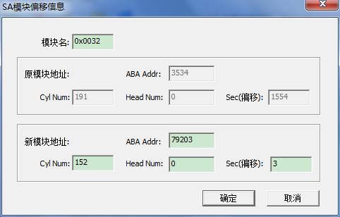
In addition to module name, original module address as well as the address you want to offset in the dialog box.
Here we fill in a default value for you, the value is calculated by the program, please take care to modify this value, otherwise it will cause damage to module data.
Click “OK” button,
it will pop up the following confirmation offset operation box. 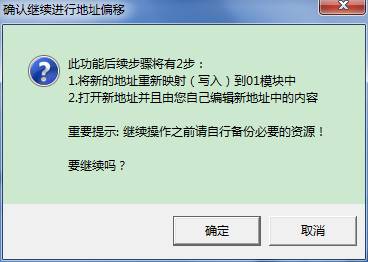
Here introduces the steps of function execution, as a precaution, it also reminds users themselves to backup resource. Once errors occur, it is easy to restore.
Click “OK” button, it will use Hexpage to open the new address corresponding to modules. You can write a new and the corresponding complete module into it to complete the work of module address offset.
Menu Position:
After clicking, it will appear the following interface:
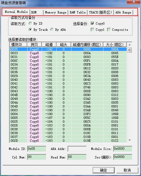
1) Module List Page
Observe the section with red line to draw, there are several pages here. Each time re-open the resource viewer, module list will open the default page. There is no detailed introduction on this page, the next you need to fill in module name needs to be read and address. Double-click any item, you can read the corresponding module displayed in Hex Editor.
2) ROM List Page
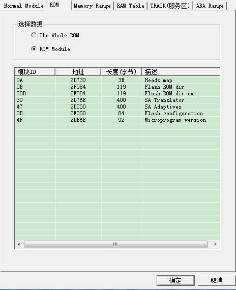
Two radio buttons controls whether to read the entire ROM or read ROM module, if you select ROM module, you can select the corresponding module in the list, click “OK” button to read data, it will display in Hex Editor.
3) Read the Memory Page
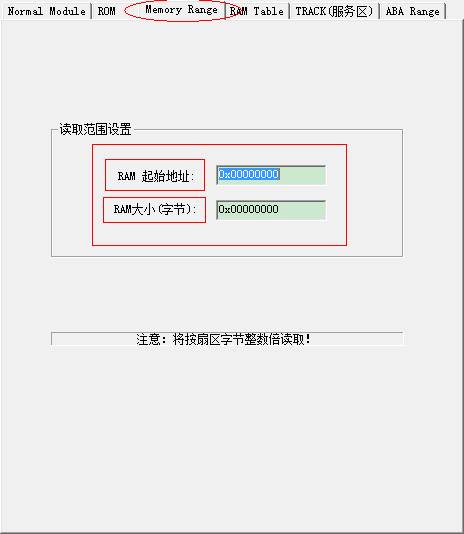
As shown in figure above, fill in address and length, then click “OK” to turn to Hex Editor to view data.
4) The RAM Memory Module List Page
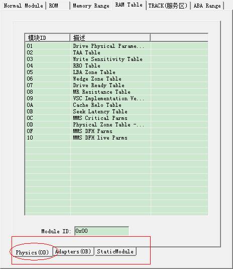
This page has three sub-pages, namely the "physical parameter page", "adaptation parameter page" and "static module list page."
The three are in list form.
Each of the three pages has an ID box, fill in the ID, click “OK” button to turn to the HEX Editor to view the data. Or double-click the list item is also available for the same purpose.
5) Track List Page
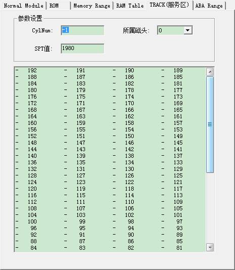
Double-click any item, or fill in tracks you want to read in the track edit box, turn to the hex editor to view the data. The belonging head can choose to read track data in which head.
6) ABA Range Page
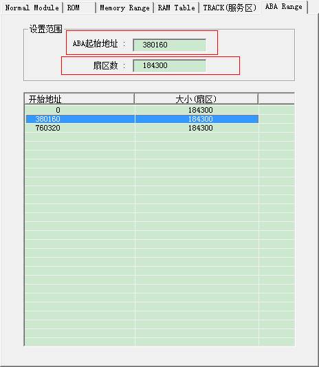
As shown in figure above,fill in the starting position of ABA,sector number,click “OK” button to read data, and turn to HEX Editor to view data. Double-click any item in the list can also acquire the same purpose.
Menu Position:
This function is the same with the function “Service Area Operation-> Search module from service area and save them,it only specifies to search 01 module, and after searching 01 module, it will automatically use 01 module that has already searched to realize the function of module list.
2.3.2 Reading and Writing Mode
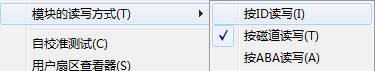
The three buttons below the right side toolbar of the main interface are the shortcut access entries for the three menu-items, it only control module list, SA module structure test as well as reading way of module in module list page on the Resource Viewer.
2.3.3 Self-calibration test
Click this function; it will remind users to set up one working folder if users don’t set up working folder. The next is to select reading mode of self-calibration script:
Click “OK”, it will enter self-calibration script:the editing page of 28 module :
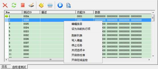
The toolbar above corresponds to the coming -out menu clicked by the right-click. Based on the menu, we will explain from top to bottom:
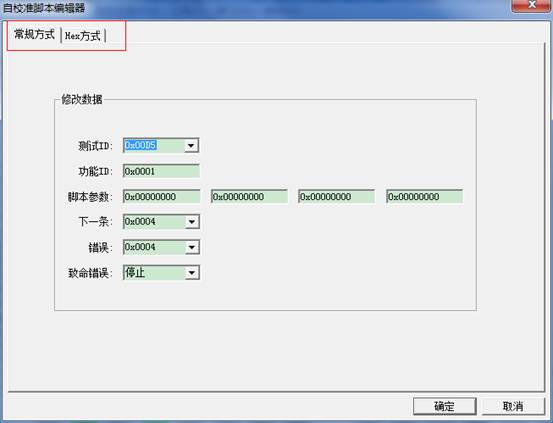
It can be divided into conventional way and Hex way. Above is the conventional way.
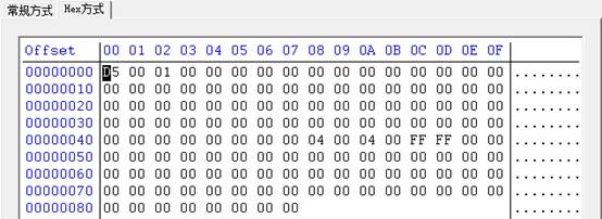
Hex way is below:(In fact, the data of items displays in Hex Editor, you can modify any one of them. )
Under any items, click the right-click, it will pop up right-click menu, and click this item, so set the item clicked just now as the current execution item.
Re-read data from HDD and refresh list data.
Write the modifying list data into HDD.
The
corresponding toolbar icon:![]() .
Click this button, or click “Start self-calibration “on the menu, it will pop
up the following interface:
.
Click this button, or click “Start self-calibration “on the menu, it will pop
up the following interface:
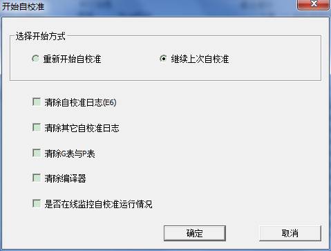
As shown in figure above,we can see that we can re-start self-calibration, or continue to from the current execution process to begin self-calibration. In addition, you can clear these logs selected before in the process of selecting. Click “OK” button to begin self-calibration. The program will detect the lasting time and the processing steps of self-calibration.
- Open the online monitoring
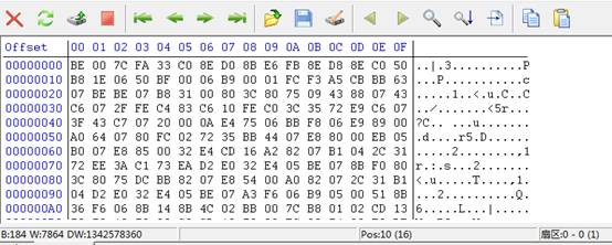
2.3.4 User Sector Viewer
This is one common tool among MRT factory module; other MRT professional tools also have this function, mainly used for viewing data of user area. Its core is a Hex Editor, here you can read and view data, also save the data read out as the file, or modify data and write into HDD again, or search data.
It will appear the following interface after you open this function:
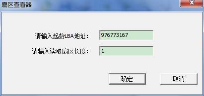
Here you can fill in the starting address and length, click “OK” button to read data and display it.
Click![]() button, you can
change another place to fill in the dialog of LBA address and length; you can
read any new address.
button, you can
change another place to fill in the dialog of LBA address and length; you can
read any new address. ![]() These 4 buttons, the middle two is as the
length you fill in for the unit, they can read the previous group of sector or
the next group of sector. The two outside buttons can jump to the foremost or
the rearmost of user data area to read data.
These 4 buttons, the middle two is as the
length you fill in for the unit, they can read the previous group of sector or
the next group of sector. The two outside buttons can jump to the foremost or
the rearmost of user data area to read data.
In addition, other buttons can realize the function of saving opening, writing into, modifying, copying, pasting, searching, turning to offset and so on.
2.3.5 Logical Scanning
It will remind you to create one working folder if you don’t create the working folder, and then it will pop up the following dialog box :
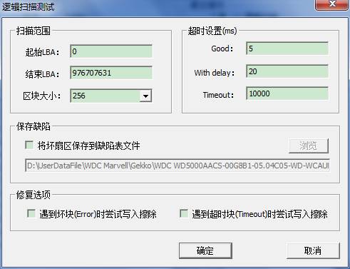
Here you can set the scanning range as well as the size of block(Block size: how many sectors it can scan each time) and timeout settings and so on.
When you check “save the bad sectors to defect table file”, the edit-box to save path of files turns into the usable statue, then click “Browse” button, you can select the save path of files. There are two items in Repair Options, the principle of repair is under some circumstances, the bad block caused by logical reasons, and then you can attempt to operation of writing into to erase. Click “OK” button to enter the scanning interface, as shown below:
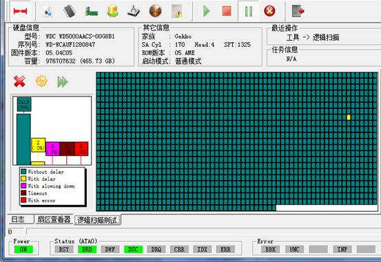
There is a color illustration in the lower left Conner of the figure above :
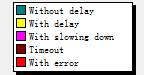 Color from top to bottom successively
expresses: good, not very good, a little slower, timeout, bad blocks.
Color from top to bottom successively
expresses: good, not very good, a little slower, timeout, bad blocks.
The top of figure shows the blocks that have already scanned ratio of the five types of blocks, with the processing of scanning, the ration changes with it.
The area on the right is a visual map scanning
There are three
buttons above scale drawings:![]() ,from left to right successively
expresses:close
this page, scanning setting(the setting page when open this function), fast forward(jump from a certain LBA and
scan again.).
,from left to right successively
expresses:close
this page, scanning setting(the setting page when open this function), fast forward(jump from a certain LBA and
scan again.).
On the main
interface ![]() ,the four buttons can control
the task of scanning:stop, pause or force quit.
,the four buttons can control
the task of scanning:stop, pause or force quit.
If we check “save bad sectors to the file” on the setting page, it will pop up LBA defect table editor when we stop scanning, and open the scanned save file, which is convenient for you to edit. The specific editing mode, please refer to LBA defect table editor.
2.3.6 CHS Defect Table Editor
Menu position:
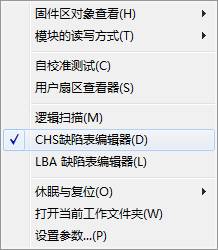
Click CHS Defect Table Editor, it will appear the confirmation box of reading and writing mode of defect table, after the confirmation of selecting, the following interface will appear:
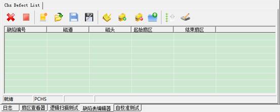
At this time,
the list is empty, when we click![]() button, we can create a new table, and then we
can add any data. Of course, the more operation for us is to open a file, and
then edit it. Beside the newly-built button, there is a button
button, we can create a new table, and then we
can add any data. Of course, the more operation for us is to open a file, and
then edit it. Beside the newly-built button, there is a button![]() ,click this button, it will
appear the following interface:
,click this button, it will
appear the following interface:
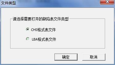
As shown in figure,we can open two kinds of file formats, CHS format and LBA format. Click “OK” button, it will appear Open File Dialog Box, you should select the file needs to be opened. If you select LBA File, the program firstly turn LBA Defect Entry Format in LBA File into CHS Defect Entry Format, and then display in the list, below is the switch process:
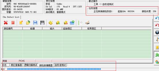
In the task information bar, it will display entries that are being converted, in progress bar; it will display the progress conversion of the current entries. After the completion of conversion, data will display in our list. Attention: open this operation may delete the original data in the list. As shown in figure below:
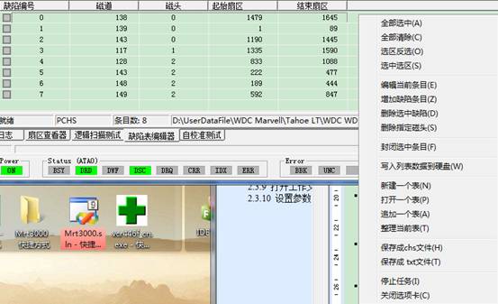
It will appear the menu like the figure above when we click the right-click in the list. The function of menu is corresponding to the toolbar’s. But some kinds of function don’t exist in the toolbar. For example the foremost select function. The usage of select function is the same with saving module’s and other list’s selection function. The next we will explain from editing:
- Edit the current entry
Click this function , it will appear the following interface:
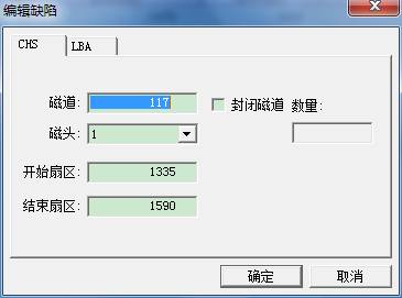
You can fill in the starting sector and the ending sector of this entry, then click “OK”, can also check “ closing the tracks”, you can fill in the number of closing tracks during the course of closing. At this time, in addition to changing the current entries, it will start from the current track number and add other entries of closing tracks. Below is LBA Editing Mode:
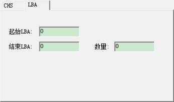
Fill in the starting from LBA and the ending of LBA,click “OK” button.
- Adding entries
The same with editing entries, the difference is that adding entries is behind the list.
3. Delete the selected defect
Using selection
function to check in front of entries need to be deleted, and then click
“Delete” the selected defects”, and you can delete the checked entries of
defects. click ![]() button
in the toolbar,it
can achieve the same purpose.
button
in the toolbar,it
can achieve the same purpose.
4. To delete the specified defects on the head
Open this function, it will appear the following interface:
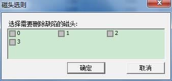
As shown in figure above, check the needed head, click OK button to delete the checked defect items on the head.
5. Closing the selected items
The same with delete function, it requires the help of select function. Click this function, all the checked items will turn into road closures items.
6. Write list data into HDD
Sort and arrange list data and then write into HDD.
7. Newly-built table, open the table
As mentioned before
8. Append a table
Similar to open a table, but it will add defect items with the opened file to the end of the existing list.
9. Save it as chs file,save it as txt file
There is no doubt that save them as file with these two kinds of formats.
10. Sort table, arrange the list data, to remove repeat and sort.
2.3.7 LBA Defect Table Editor
It will appear the following interface if you open this function:
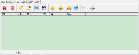
The same with CHS Editor,![]() button,you can open one file, but it
only accepts the lba format file.
button,you can open one file, but it
only accepts the lba format file.
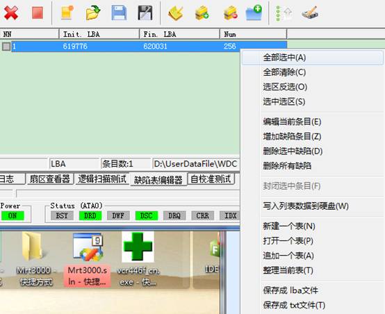
The menu will also appear in the list, as shown in figure below:
- Edit the current item, add an item.
Open this function, it will appear the following interface:
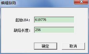
It is very simple, fill in the starting LBA and defect length, and click OK to edit an item or add an item.
- Delete, delete all
Delete, delete the checked item
Delete all, which means to empty tables
- Newly-built table , Open table, appended table, sorting table
Newly-built table,it will clear the original table, create a new empty table
Open table, open a file with lba format and display items in the file
Appended table, open a file with lba format, and the file items are appended to the end of the list.
- Write list data into HDD
Click ![]() to achieve the same
purpose, it will appear the following prompt and asking dialog box when we
click to open this function:
to achieve the same
purpose, it will appear the following prompt and asking dialog box when we
click to open this function:
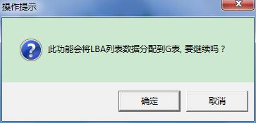
Yes, this function will allocate list data to G-list, performing the task takes some certain time, please attention:
Before deciding, you had better firstly click ![]() button to sort list data so
as to allocate or save time when use CHS editor to open and carry on switch
operation.
button to sort list data so
as to allocate or save time when use CHS editor to open and carry on switch
operation.
2.3.8 Sleep and Reset
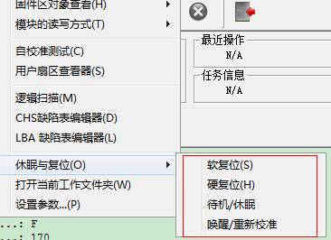
![]() Corresponding to four buttons above toolbar on
the main interface, please refer to the main program instruction for use for
the detailed description.
Corresponding to four buttons above toolbar on
the main interface, please refer to the main program instruction for use for
the detailed description.
2.3.9 Open the working folder
It is used to locate the current working directory in using; the working directory holds all the current HDD firmware information.
2.3.10 SET Parameter Settings
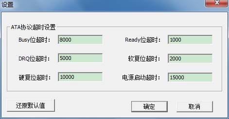
As shown in figure ,you can set timeout parameter.