Hitachi-ARM(Hitachi ARM Series) Professional Tools Description
These documents are derived from MRT Firmware Laboratory.
For more information, please visit our website http://www.mrtexp.com
Content
1 Hitachi-ARM Startup Interface and Main Interface
1.1 Normal Circumstance and Clear Password Function………………………..3
2 Hitachi-ARM Menu Structure and Main Function
2.1 Diagnosis…………………………………………………………………….4
1. Basic Information……………………………………………………….5
2. Area Service Operation…………………………………………………..5
(1)Full Backup Hard Disk Resources…………………………………….
(2)Save ROM……………………………………………………………6
(3)NV-RAM Operation………………………………………………….6
(4)Backup module object………………………………………………..9
(5)Module Batch Write………………………………………………....10
(6)SA Structural Testing………………………………………………..10
3. Format……………………………………………………………………14
4. Defect Operation……………………………………………………..12
(1)View P-List………………………………………………………… 13
(5)G-List To P-List……………………………………………….13
(3)Clear G-List………………………………………………………………….13
6. Clear S.M.R.T…………………………………………………………...14
8. Solve Common Problems……………………………….…………….15
(1)Virtual Translator……………………………………………………15
2.2 Tools…………………………………………………………………..…….16
1. Firmware Object View………………………………………………….16
(1)Module List…………………………………………………………16
(2)View and Edit Hard Disk Resource……………………………… 17
3. User Sector Viewer……………………………………………………...19
2. Sleep and Reset………………………………………………………………….18
4. Parameter settings………………………………………………………..19
5. Open the Current Working Directory…………………………………….20
Hitachi-ARM Startup Interface and Main Interface
When the program starts, it will firstly pop up the Read Countdown Dialog to carry on the initialization work before starting, if the initialization works success, it will enter the selection interface of hard disk type. As shown in figure 1.
If the hard disk has password, it will show the interface, as shown in figure2.
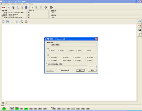
Figure1(Hitachi-ARM Normal Startup Interface)
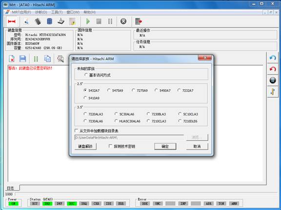
Figure2(Hitachi-ARM detects the encryption of hard disk to start the interface)
At this time users can click “Clear the Password” button, it will firstly require users to set the current working directory; the working directory is used to backup NV-RAM and SEIC module. After setting the working directory, it will pop up the dialog box as shown in figure in 2-1.
.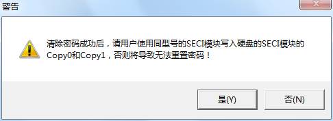
Figure2-1 Clear the password prompt dialog box
Click“OK”button, it will pop up the dialog box as shown in figure in 2-2.
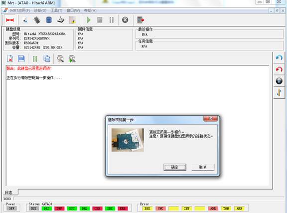
Figure2-2 Shortcut connection with hard disk prompt box
Click“OK”button, it will perform the first step of operation, it may be for a long time to wait for the hard-ready process, please wait patiently. After the successful operation, it will perform the second step, as shown in figure 2-3.
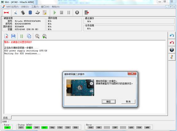
Figure2-3The prompt box of connecting the hard disk
Click“OK”button, it will perform the second step of operation, it may be spend a long time to wait for the hard-ready process, please wait patiently. The final result will display in the log page, as shown in figure 2-4.
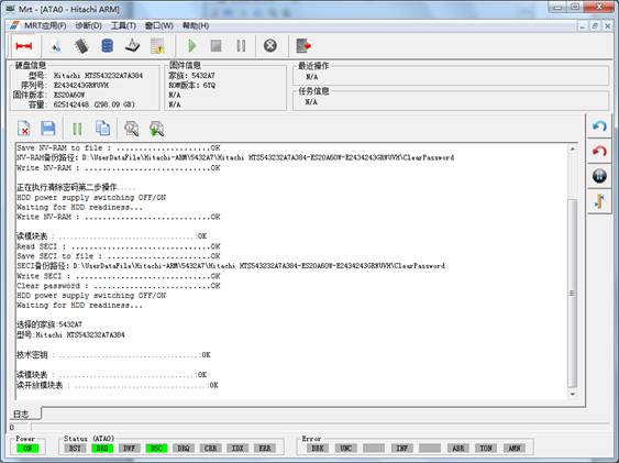
Figure2-4 Clear the password successfully
Clearing the password turns out a success, the hard disk can correctly read modules, but users won’t be able to reset the password, if users need to repair the function of resetting the password, please use the same type of SECI module to write into Copy0 and Copy1 of the hard disk SECI module.
The program will automatically detect the series, if it fails to detect the series; users are required to manually select the series. The program will load the technology key according to this series number as well as read module list and other firmware information. Users can check the module list loaded from the file and detect the technology key before starting the program. After selecting the hard disk serial number, users can click “OK” button to enter the main Hitachi-ARM interface, if it fails to load the technology key and if users check the program “Detection on Technology Key”, it will attempt to use the entire possible technology key to start the hard disk. If users check the module list program loaded from the file, it will directly load the file selected by users into the module list, as shown in figure 3.
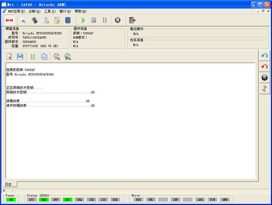
Figure3(the Main Hitachi-ARM Interface)
Initialization information in the process of starting the hard disk will display in the log page, including loading technology key, loading module list and other basic information.
Hitachi-ARM Menu Structure and Main Function
Hitachi-ARM series HDDs professional tools’ main menu is “Diagnosis” and “Tools” menus.
Each time users open the factory program to save the file or write into, it will pop up the establishment of working directory dialog, as shown in figure 3.
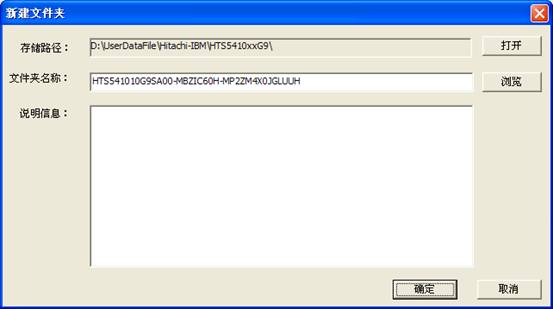
Figure 3 Setting up working directory
Please refer to “Description of the Main MRT Program-6 Working Directory and Save File Setting”, if users want to know more details about the working directory and the content structure, it will not provide the description about saving file and working directory below.
After setting up the store directory, please click “OK” to complete the establishment of working directory.
2.1 Diagnosis
“Diagnosis” menu(As shown in figure 2.1)provides some basic operations on the hard disk, for example read, write, view and edit the module list and other operation to the hard disk firmware.
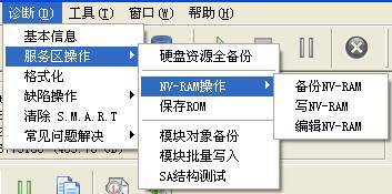
Figure2.1(Diagnosis)
1. Basic Statue of the Hard Disk
“Basic Statue of the Hard Disk”provides a view of the current statue of the hard disk(As shown in figure2.1-1),including the hard disk belonging to family, each firmware serial number, whether to set passwords and other information and provides the function of reloading the module and re-identification of the device.
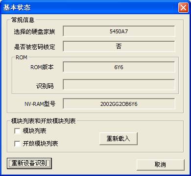
Figure2.1-1(Basic Statue of the Hard Disk)
2. Service Area Operation
“.Service Area Operation”provides "full backup hard disk resource", "Save ROM", "NV-RAM operation", "Module object backup", "module batch write", "SA structure test" and other function.
(1)Full Backup Hard Disk Resource
“Full backup hard disk resource” is used to backup the entire recourse of the hard disk, including:ROM、NV-RAM、Module Resource(As shown in figure2.2-1).
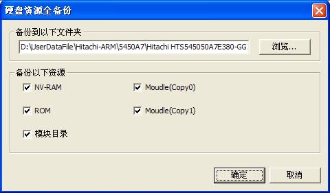
Figure2.2-1(Full backup hard disk resource)
(3)NV-RAM Operation
“NV-RAM Operation”provides the operation related to NV-RAM, including “Backup NV-RAM”、“Write into NV-RAM”、“Edit NV-RAM” and other series of function.
(a)Backup NV-RAM
“Backup NV-RAM” reads information inside NV-RAM(Non-volatile random access memory)from the hard disk and saves it as the file, as shown in figure 2.2-3.
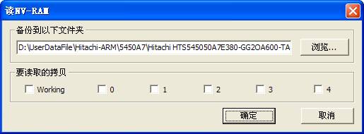
Figure2.2-3(Read the NV-RAM)
Hitachi-ARM Serial hard disk NV-RAM has number of Copies,mark the current use as Working,others as backups.
Click“Save”button to complete this operation, the execution results and the full saving path will display the log page.
(b)Write into NV-RAM
Write the saving NV-RAM information into the hard disk, as shown in figure 2.2-1.
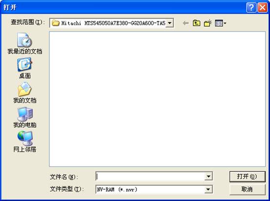
Figure2.2-1Write into NV-RAM
The program will open the default folder and list the entire saving NV-RAM, users select one NV-RAM and click “Open” button or double -click this file to write NV-RAM into the hard disk.
(c)Edit NV-RAM
NV-RAM is such a area to save the hard disk of each firmware version, number of heads, the entrance address and other information of area, “Edit the NV-RAM” provides the function of modifying and writing into parameters, as shown in figure 2.2-5.
After editing by users, click “OK” button to perform this operation, the operation result will display in the log page
(2)Save ROM
“Save ROM”is to save information inside ROM as the file, (as shown in figure2.2-2), the saving result will display in the Log page.
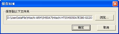 Figure 2.2-2Save ROM
(3)Backup module object
“Backup module object”is to save all the normal modules in the hard disk as the file.(As shown in figure2.2-3).
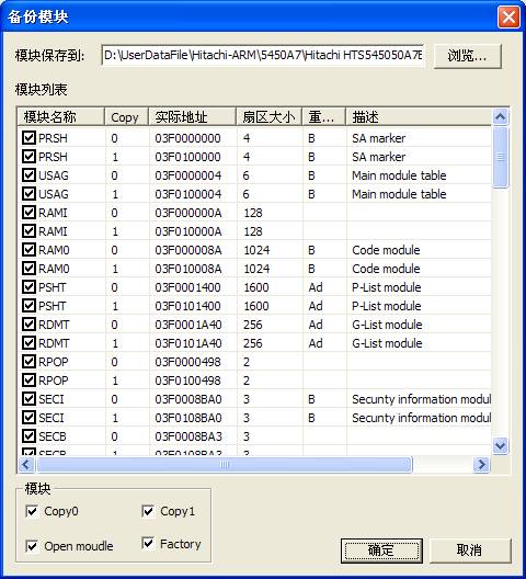
Figure2.2-3(Backup module object)
Users can set the saving folder, and they can also selectively check the modules need to be saved.
After setting the saving option, click “OK” button to perform this operation, the operation result will display in the log page.
(4)Module batch write
“Module batch write”will write the saving module into the hard disk, as shown in figure 2.2-4.
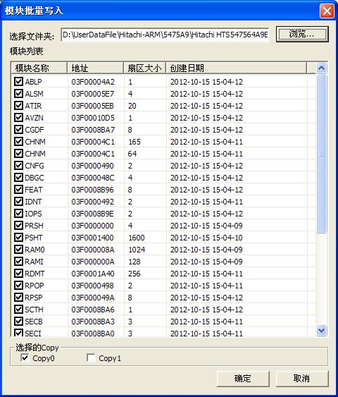
Figure2.2-4(Module batch write)
If users set the working directory, the program will open the current working directory \by default; otherwise the default is Drive C. According to the settings when users save the module,there are three kinds of backup folders to choose: Copy 0, Copy1, Copy F. After selecting the backup folder, it will list all the modules that have already been backed up, and then users can selectively check the modules need to be written into.
(5)SA Structural Testing
“SA Structural Testing” is used to test whether each module can be read normally, the test result will display in the log page.
Users can check the heads need to killed according to the practical situation, “Setup Mode” can choose "Automatic" or "Manual"; “Automatic”mode for the program with two heads, the default is 01mode, for those programs with more than two heads, the default is 02mode. “Manual”mode, users can change the translation mode manually, the selectable modes are 01,02,03,12 and several models, the corresponding scale is from 0-3.
3. Defect operation
Defect operation" provides the function of "View the P-List", "Clear the G-List", "G-List to P-List" function(As shown in figure2.4).
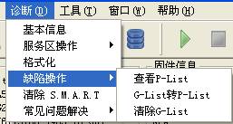
Figure2.3 Defect operation
(1)View the P-List
“View the P-List”provides a view to the P-list, it will firstly ask users to save the defect list that has read(As shown in figure2.3-1).
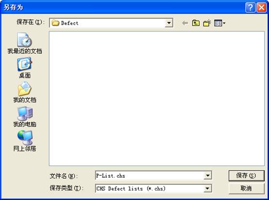
Figure 2.3-1(View the defect)
After the completion of saving the P-list, it will display all the “Basic defect table” in the hard disk(As shown in figure2.3-2).
(2)G-List to P-List
“G-List to P-List” is used to turn “Growth defect list” into “Basic defect table”.
(3)Clear the G-List
Clear the G-List will empty the“Growth defect list” in the hard disk. These defects can be found in the process of operate the hard disk, also can be found in the process of formatting, and also can be found in the process of the automatic or use of specific formatting command to reallocate.
4. Formatting
Formatting is used for the lower level format to the hard disk, as shown in figure 2.5-1. Users can specify the area need s to be to formatted.
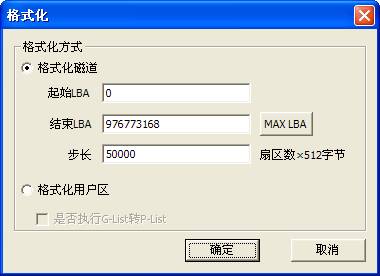
Figure 2.4-1(Formatting)
“Factory Format”,users can specify the starting LBA and the ending LBA as well as how many sectors to be formatted per time. The maximum number of error is used to mark the allowing wrong number of sectors, when this maximum number of error is exceeded, it will stop formatting.
5 Clear the S.M.R.T
Self Monitoring, Analysis and Reporting Technology (SMART) are designed to protect users’ data and reduce the possibility of sudden system downtime caused by the expected degradation or the malfunction. By monitoring and storing critical performance and standard parameters, SMART device attempts to predict the time close to the condition of degradation and malfunction. If the host system knows a non-reliable condition, the host system is allowed to warn users the risk of closing to lose data and suggests users to take appropriate measures.
After the execution of "Clear the S.M.R.T", it will empty all the recorded parameters.
6. Solve common problems
(1) Virtual Translator
“Virtual Translator”mainly focuses on unrecognizing in the process of the hard disk initiation, the damage to translator after loading two times.(As shown in figure2.8-1).
The function can be divided into two ways:Manual execution, each time the hard disk can’t be recognized, it needs the manual execute this operation. Automatic execution,this way needs to turn to DR (data copy program) and check the use of the factory copy.
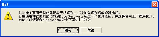
2.6-1(Virtual Translator)
2.2 Tools
“Tools” menu has:"Firmware Object View", "Standby and Reset", "User Sector Viewer”and other submenus.(As shown in figure2.2).
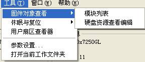
Figure2.2(Tools)
1. Firmware object view
(1)Module list
Module list is used to display, modify each of module information inside the hard disk. As shown in figure 2.2-1.
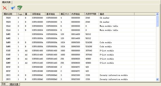
Figure 2.2-1Module List
Double
click any line to load the module into Hex Editor, as shown in figure 2.2-2. Users can
modify, save, and write into the hard disk and other basic operation.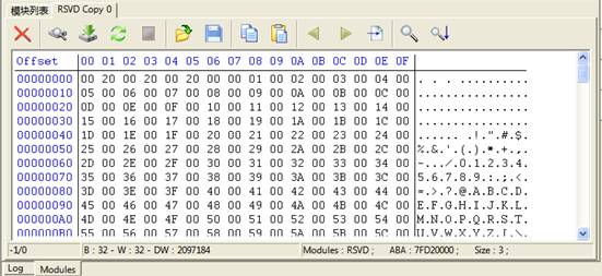
Figure2.2-2 16 Hex Editor
2. View and Edit Hard Disk Resource
View and Edit Hard Disk Resource is used to view the information of each hard disk firmware and edit the firmware resource, as shown in figure 2.2-3.
The function can be divided into two parts: Module and RAM/NV-RAM. Module will display all the firmware information of the hard disk, RAM/NV-RAM will display the information read from the chip, including the information inside ROM、NV-RAM, RAM.
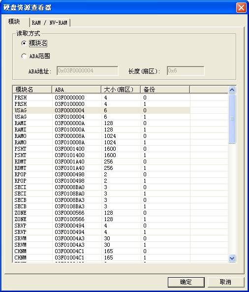
Figure2.2-3 View and Edit Hard Disk Resource
Users can select any line, or use ABA range to manually enter ABA address and length. Address is expressed in hexadecimal, start with 0x, length is expressed in decimal notation,click “OK” button to load this module, or double click any line in the list to load this module. After loading the module, it can be modified. About hex editor, refer to the aforementioned.
2. Standby and Reset
“Standby and Reset”menu provides the conventional operation on HDD, please refer to “Main MRT Program Description” about “Soft Reset ”、“Hard Reset”、“Reset”、“Standby”.
3. User Sector Viewer
“User Sector Viewer”is used to view and edit specified sector. As shown in figure 2.2-4.
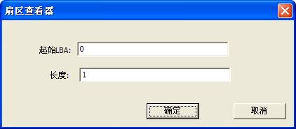
Figure2.2-4 View and edit user sector
After users filing in the starting LBA and the length, click the "OK" button to read out the designated sector, edited in the Hex Editor. (As shown in figure2.2-5)
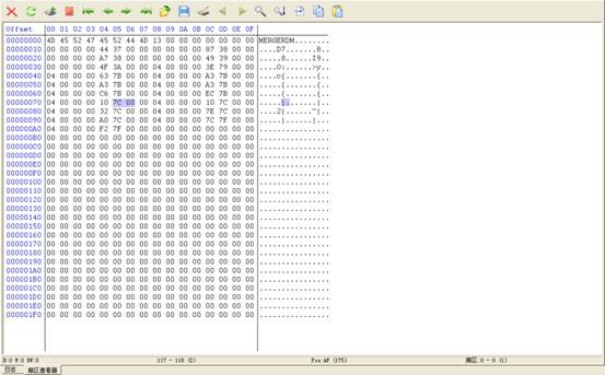
Figure2.2-5(User Sector Viewer)
4. Parameter settings
Parameter settings is used to set ATA timeout agreement(As shown in figure2.2-6)
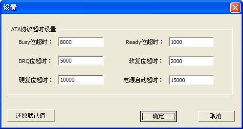
Figure2.2-6(Parameter settings)
5. Open the Current Working Directory
Open the Current Working Directory is used to locate in the current working directory in use, this working directory holds all the information about the current hard disk firmware.