The new version of MRT hardware card introduction and IDE interface instruction for use
These documents are derived from MRT firmware laboratory.
For more information, please visit our website http://www.mrtexp.com
The new version of MRT hardware card increase IDE interface and the function of FLASH chip programming, and optimize a lot of design on the basis of the old version. The new version of MRT hardware card adopts gray as the board background, the design is more beautiful and more gradable.。The new version of MRT hardware card is such kind of hardware card based on PCIE slot, which can be inserted like a network card, sound card or graphics card on the computer motherboard PCIE expansion slot, on the hardware card provides two SATA interfaces and an IDE interface, the hard disk waiting to be repaired is connected to the interface provided by the hardware card. The repair card adopts the special hardware technology, which makes it possible to enable a factory-level operation on the hard disk, in the case of other software and operating system can’t recognize the disk, MRT can still recognize and deal with the hard disk. Meanwhile,MRT product provides a wealth of accessories, including terminal serial port and programming tool, to fully meet the needs of a variety of use. MRT programmer tools can read and program ROM chip on the hard disk, and is not only limited to the hard disk, all in line with ROM chip of the SPI interface, including computer motherboard BIOS chip. It can be brushed to write by MRT programmer and can be used to repair the bad hard disk ROM brush, or the bad motherboard BIOS brush etc..
The new version of MRT hardware card still consists of two parts: the main card and power supply board, main card provides two SATA interfaces and an IDE interface for connecting a hard disk to be repaired. Power supply board outputs two sets of power for connecting a hard disk to be repaired. The two sets of power can be automatically controlled by the MRT software, can be very easily connected to the software interface or cut off the power supply of hard disk to be repaired,which is particularly important for hard disk repair and data recovery work. It makes the software can be imaged on the fault disk data in an unattended mode, the software can automatically cut off the power and restart the hard disk when the hard disk hang up or loss of response without manual intervention.
Below is the new version of MRT hardware card:
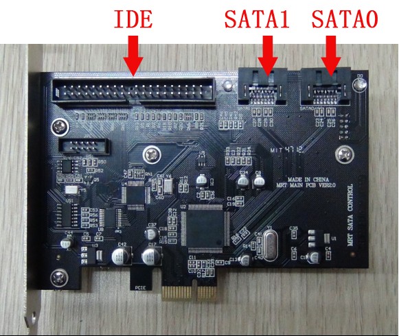
As shown above,the new version of MRT hardware card consists of two SATA interfaces and an IDE interface. Order from right to left is followed SATA 0 Interface, SATA 1 interface, IDE interface.
Below is the part screenshot of the main MRT software tool interface:
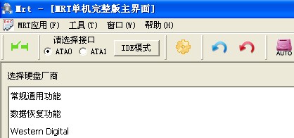
In the main software toolbar interface, you can see the program "Please select the interface", which has ATA0 interface and ATA1 interface can be selected. At any time,users can choose to work on ATA0 interface or ATA1 Interface. There are only two interfaces in software, but there are there interfaces in the hardware card, they are SATAO interface, SATA1 interface and IDE interface. So how to use IDE interface?To solve the problem, the main interface adds a “IDE Mode” button. When“IDE Mode” button is upspring, IDE interface on the hardware card on the card is killed and in the state of invisibility. At this point, ATA0 on the software represents SATA0 interface on the hardware, ATA1 on the software represents SATA1 interface on the hardware. This case is consistent with the old version of the MRT hardware card. When users need to use IDE interface, press “IDE mode”button,now“IDE mode”button is in the state of pressing,as shown below:
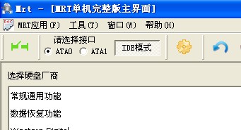
When“IDE Mode”button is in the state of pressing, SATA1 interface on the hardware will be killed and in the state of invisibility, but IDE interface will be activated. This moment ATA0 on the software still represents SATA0 interface on the hardware, but ATA1 on the software represents IDE interface. At this time, all operation did by users on the ATA1 interface is the operation of hard disk connected to the IDE interface
IF users want to re-use SATA1 interface on the hardware,so simply click “IDE mode”button,then the button will upspring, at this moment ATA1 on the software represents SATA1 interface on the hardware, and IDE interface on the hardware will be killed and in the invisible state.
In fact,the rule of switching is very simple, description like this:At any time,ATA0 on the software always represents SATA0 on the hardware,but ATA1 on the software represents SATA1 interface on the hardware when “IDE Mode”button is upspring, and it represents IDE interface on the hardware when “IDE Mode”is in the state of pressing. So we can know the current situation of interface distribution by observing the appearance of “IDE Mode” button. Attention, the state of “IDE Mode”button is automatic memory, that is to say,if it is in the state of pressing, and then exits the MRT, and then restart MRT program,at this moment the button is still in the state of pressing, ATA1 still represents IDE interface.
Special attention:Because of this method of use, it is easy for users to confuse whether the current use of hard disk is the disk of SATA1 interface or the disk of IDE interface. Therefore, all the tools except the main interface in MRT should turn off to change the state of button. This will reduce the possibility of mistakes.
Picture below displays the appearance of power supply board at the back side of the new version of MRT hardware card.:
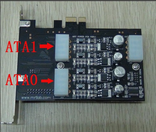
As shown above, Power seat is at the upper right side of hardware card and it is connected to the motherboard's power input and then MRT output two paths of power available to connected to the hard disk. As the arrow shows, when the power of ATA0 and ATA1 outputs connection, they should be consistent with the data interface of hard disk.
In addition to adding new IDE interface, the new version of MRT hardware card also adds ROM chip programming function, which can read and write, erase and program the common FLASH memory chip as well as doing other operation on it, it is not only limited to the hard disk ROM chip, but also including motherboard BIOS chip and all those ROM chips of using SPI interface can receive better support. This design is convenient for users, and save the additional investment to buy expensive dedicated programmer for users. To use MRT programming function, programmer seat attachment sent by us with the card should be connected to MRT hardware card. The method of connecting as shown below:
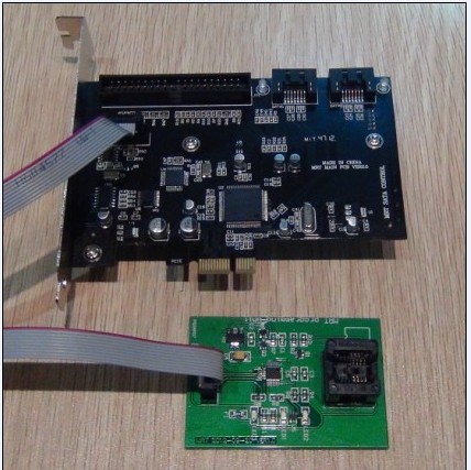
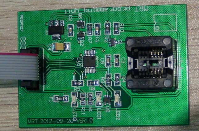
The method of programmer seat and hardware card schematic diagram:
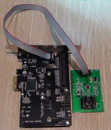
As shown above, after connecting well, and the next you need to install MRT hardware card to the host, and then put ROM chip needs to be programmed into programmer seat and fix it well, after this you can use programmer tools provided by MRT for processing operation.。
The new version of MRT hardware card results show:
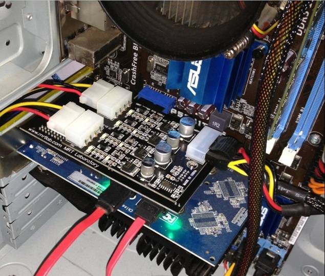
MRT SATA hard disk repair tool firstly adopts PCIE interface and native SATA transmission, providing faster and more stable data transmission. We adopt a variety of optimization techniques on the hardware, and comprehensively improve the capacity of hard disk repair. Our software supports a variety of brand series of hard disk and we provide continuous upgrade service. May MRT tool become your most powerful assistant, we can't develop without your support!
MRT Firmware laboratory