MRT Main Program Description
From MRT Lab: http://www.mrtexp.com
Content
1. Main Interface
1.1 Menus and toolbars structure……………………………………………….2
2. Reset process and principle
2.1 Hard Reset…………………………………………………………… …….4
2.2 Soft Reset……………………………………………………………………4
2.3Reset…………………………………………………………………………4
2.4Standby Mode……………………………………………………………….4
6. Working directory and description of saving the file
6.1 Working directory structure…………………………………………………5
MRT Main Interface
MRT Main Interface provides the display of each module and start function. MRT adopts the module extension structure and consists of a main program and many modules, each module can provide a separate function, you can upgrade the module, or you can also add new module. Main interface as shown in figure 1.
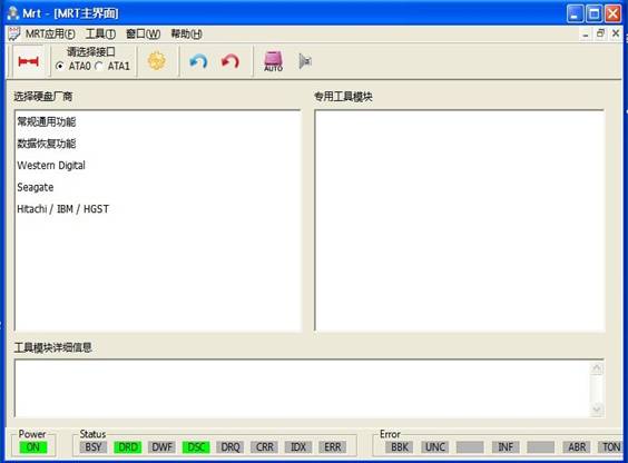
Fingre1 Main Interface
1.1 Menus and Toolbars
The main menu is “MRT Application” and “Tools”,“MRT Application Menu” provides some operations on the current window, "Tools menu" provides automatic detection of hard disk manufacturers, module startup and system settings function.
Toolbar provides shortcuts to certain menu
functions,![]() “Power”button, MRT PCIE can
provide stable voltage of 5V for HDD;
“Power”button, MRT PCIE can
provide stable voltage of 5V for HDD;![]() “Port Selection”,MRT supports
two native SATA interfaces(ATA0 and ATA1)corresponding to two SATA interfaces on MRT PCIE
control card, you can connect two hard disks simultaneously;
“Port Selection”,MRT supports
two native SATA interfaces(ATA0 and ATA1)corresponding to two SATA interfaces on MRT PCIE
control card, you can connect two hard disks simultaneously;![]() “System
Settings”button(same as the
menu item "Tools - System Settings”),(As shown
in figure1.1-1)
“System
Settings”button(same as the
menu item "Tools - System Settings”),(As shown
in figure1.1-1)
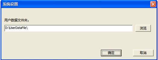
Figure1.1-1System Settings
Used to save information of user's system settings;![]() soft reset、hard reset;
soft reset、hard reset;![]() “Auto Detect
"button is used to automatically detect the hard disk model;
“Auto Detect
"button is used to automatically detect the hard disk model;![]() "Start" (same as the menu item
"Tools - Automatic detection and start") click this button to enter
the designated tools, you can also double-click the tools need to be open.
"Start" (same as the menu item
"Tools - Automatic detection and start") click this button to enter
the designated tools, you can also double-click the tools need to be open.
Reset process and principle
There are three types of reset in the ATA:
(1)Power-on reset: The device performs a series of circuit diagnostics, rotating machines, test speed and other mechanical parameters, and set the default value;
(2)Hard Reset: The device performs a series of circuit diagnostics, and set default values;
(3)Soft Reset: Reset Device Interface Circuit.
2.1 Power-on Reset
The signal from the host system (Perst PIN), power-on reset pin (Reset pin) is "yes", and keeps at least 25us after the voltage stability within the allowable range, then "no", unless some events require a device reset.
ATA device does not recognize a reset signal shorter than 20ns.The device can respond to any more than 20ns of signal set to 1 and the device recognizes one of equal or greater signal 25us.
2.2 Hard Reset
If the device needs, MRT will send a hard reset signal to the device's hardware control registers, after reading the control register value, the device will trigger a hardware reset if the value is "yes". And keeps at least 25us after the voltage stability within the allowable range, then is "no".
2.3 Soft Reset
Some devices require software reset signal not less than 5us.
When user requests soft reset device, MRT will set the "positive" to the soft reset of the device control register (SRST). The BSY statue register will remain for at least 400ns, and test the value of SRST. If the value is "positive", the device will perform initialization and diagnostic procedures, and then the device may recover to the default state, at the same time set the status register ERROR bit and wait for the host to clear SRST bit.
2.4 Standby Mode
The host sends a command to the device command register and set the control register state, and then the device goes to sleep state, the hard disk stops and waits for the host to send commands.
2.5 Reset
"Reset" is to wake hard disk up from sleep state and re-initialize the device information.
Working directory and description of saving the file
6.1 Working directory structure
MRT default working directory is D:\UserDataFile,,in this directory MRT defaults to create a folder for each module, As shown in figure 6-1.
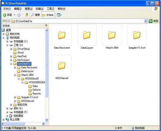
Figure 6-1 Working Directory
For the first time to use the function of saving information in the program, it will ask users to set the saving path, as shown in figure 6-2. Users can modify the file name and change the saving paths, the dialog box will automatically list all subdirectories in the current directory, it is recommended to use the default path.
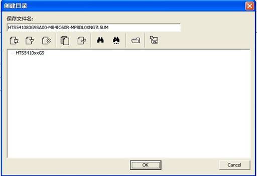
Figure 6-2 Creating Working Directory
The default will create a new folder in the current use of the module folder; the folder name is the current hard disk model -serial number - firmware version. The new folder will create a folder for each firmware of the hard disk to save the firmware information read by users. Such as the establishment Rom, Data and other folders in the Hitachi-IBM folder is to save Rom information read by users from the hard disk and data information,and it will provide firmware instruction dialog box(as shown in figure 6-3) when you save the information of firmware. And save the user's instructions as a text, the location of saving is in each firmware folder.
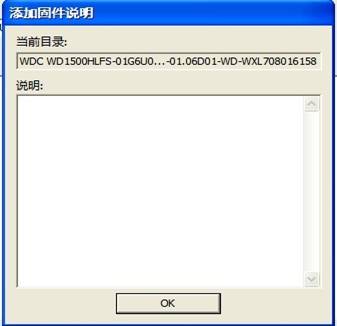
Figure6-3 Firmware Description
Each module of the program has multiple functions need to use a file to save, in the other modules description won’t give a detailed introduction of the directory structure any longer.