Hitachi-IBM Tools Description
These documents are derived from MRT Firmware Laboratory.
For more information, please visit our website http://www.mrtexp.com
Content
1 Hitachi-IBM Startup Interface and Main Interface
1.1 Normal Circumstance and Clear the Password Function……………………3
2 Hitachi-IBM Menu Structure and Main Function
2.1Dignosis……………………………………………………………………..8
1. Basic Information ………………….…………………………………….9
2 .Service Area Operation…………..……………………………………….9
(1)Full Backup Hard Disk Resource………….………………………..10
(2)Save ROM………………………………………………………..10
(3)NV-RAM Operation………………………………………………….10
(4)Backup Module Object……………………………………………….14
(5)Module Batch Write…………………………………………………..15
(6)SA Structural Testing………………………………………………..16
3. Kill head……………………………………………………………….17
4. Defect operation……………………………………………………....18
(1)View P-List………………………………………………………..19
(2)Clear P-List…………………………………………………….….21
(3)Clear G-List………………………………………………………21
(4)Edit t G-List……………………………………………………..…21
(5)G-List to P-List…………………………………………………21
5. Format…………………………………………………………………….23
6. Clear S.M.R.T………………………………………………………..23
7. Load LDR…………………………………………………….......…24
8. Editing HDD ID…………………………………………………………25
2.2 Tools………………………………………………………………..…...25
1. Firmware Object Viewer………………………………………………25
(1)Module List……………………………………………………….26
(2)View and Edit Hard Disk Resource……………………………….27
2. Standby and Reset……………………………………………………….27
3. User Sector Viewer……………………………………………………28
4 Logical Scan………………………………………………………30
5. Parameter Settings…………………………………………………30
6. Open the current working directory………………………………30
Hitachi-IBM Startup Interface and Main Interface
When the program starts, it will firstly pop up the Read Countdown Dialog to carry on the initialization work before starting, if the initialization work turns out a success, it will enter the selection interface of hard disk type. As shown in figure 1.
If the hard disk has password, it will show the interface, as shown in figure2.
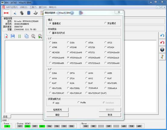
Figure1 Under normal circumstance the selection interface of HDD model
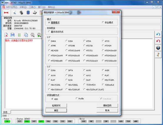
Figure2 the selection interface of HDD model after setting password lock
At this moment, users can click “Clear password” button, it will pop up the dialog box as shown in 2-1.
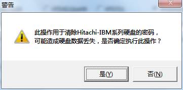
Fugure2-1 Clear password prompt dialog box
Click “Ok” button, it will pop up the dialog box as shown in figure 2-2. During the course, users will be asked to select the working directory to backup necessary files, when it fails to clear the password lock, users can manually recover them according to the backup files.
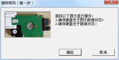
Figure2-2 Shortcut connection with HDD prompt box
Click “OK” button, it will perform the first operation; it will carry on the second operation after the success of the first operation. As shown in figure 2-3.
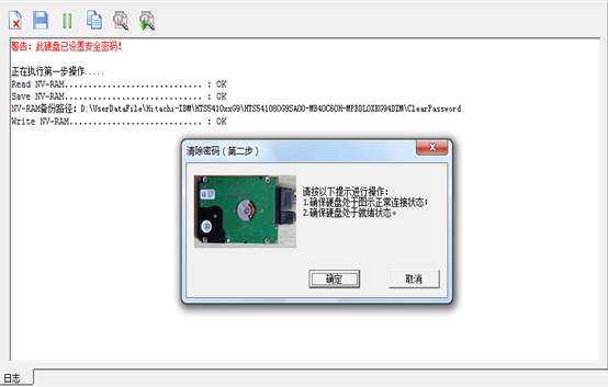
Figure2-3 the prompt box of connecting HDD
Click “OK” button, it will perform the second operation and the final result will display in the log page, as shown in figure 2-4.
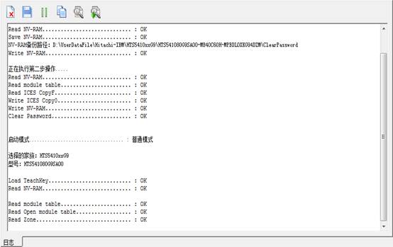
Figure 2-4 the success of clearing the password
The program will automatically detect the model, if it fails to detect the model; users are required to manually select the model. The program will load the technology key and read module lists, NV-RAM and other firmware information according to this model. After selecting the hard disk model, users can click “OK” button to enter the main Hitachi interface, as shown in figure3.
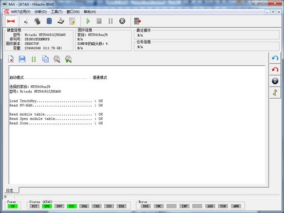
Figure3(The main Hitachi interface)
Initialization information in the process of starting the hard disk will display in the log page, including whether successfully load technology key and module lists and other basic information.
Hitachi-IBM Menu Structure and Main Function
The main menu of Hitachi-ARM Series Hard Disk Professional Tools is the “Diagnosis”and “Tools”menu.
Each time users open the factory program to save the file or write; it will pop up establish working directory dialog, as shown in figure 3.
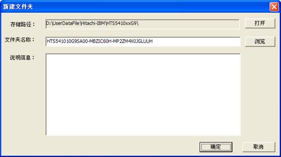
Figure 3 Setting up working directory
Please refer to “Description of MRT main Program-6 Working Directory and Save File Setting”, if users want to know more details about the working directory and the content structure, it will not provide the description about saving file and working directory below.
After setting up the store directory, please click “OK” to complete the establishment of working directory.
2.1 Diagnosis
“Diagnosis” menu(As shown in figure 2.1)provides some basic operation on the hard disk, for example Backup HDD resource, Detect Operation, Formatting and other basic operations.
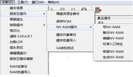
Figure 2.1(Diagnosis)
1. Basic Statue of the Hard Disk
“Basic Statue of Hard Disk”provides a view of the current statue of the hard disk(As shown in figure2.1-1),including the hard disk belonging to family, serial number, firmware version, whether to set passwords and other information , and provides the function of reloading the module and re-identification of device.
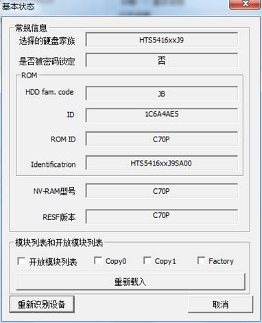
Figure2.1-1(Basic Statue of the Hard Disk)
2. Service Area Operation
“.Service Area Operation”provides "full backup hard disk resource", "Save ROM", "NV-RAM operation", "Module object backup", "Module batch write", "SA structure test" and other function.
(1) Full Backup Hard Disk Resource
“Full backup hard disk resource” is used to back up the entire recourse of hard disk, including:ROM、NV-RAM、Module Resource、Module List Table(Main module list、Open module list、ZONE).(As shown in figure2.2-1)
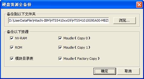
Figure2.2-1(Full backup HDD Resource)
(2)Save ROM
“Save ROM” is to save information inside ROM as the file.(The default file name:ROM.bin),(As shown in figure 2.2-2). The save result will display in the log page.
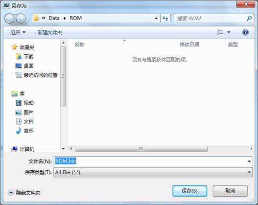 Figure 2.2-2Save ROM
(3)NV-RAM Operation
“NV-RAM Operation”provides the operation related to NV-RAM, including “Backup NV-RAM”、“Write into NV-RAM”、“Edit NV-RAM” , “Calibration of NV-RAM entry address” and other series of function.
(a)Read NV-RAM
“Read NV-RAM” is to read NV-RAM from hard disk NV-RAM(Non-volatile random access memory)and save it as the file(The default file name:NV-RAM.Nvr),as shown in figure2.2-3.
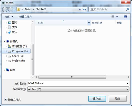
Figure2.2-3Read NV-RAM
Click “Save”button to complete the operation, the execution result and the full path of saving will display in the log page.
(b)Write NV-RAM
Write the saving NV-RAM information into hard disk, as shown in figure 2.2-4
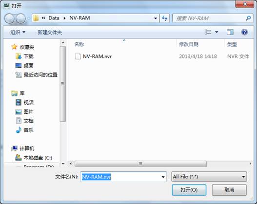
Figure 2.2-4Write NV-RAM
The program will open the default folder and list the entire saving NV-RAM in the folder, when users have already selected one NV-RAM file and click “Open” button or double click this file to write NV-RAM into hard disk.
(c)Edit NV-RAM
NV-RAM is such a area to save each hard disk firmware version, number of heads, the entrance address and other information of area “Edit NV-RAM” provides the function of modifying parameters and writing into, as shown in figure 2.2-5.
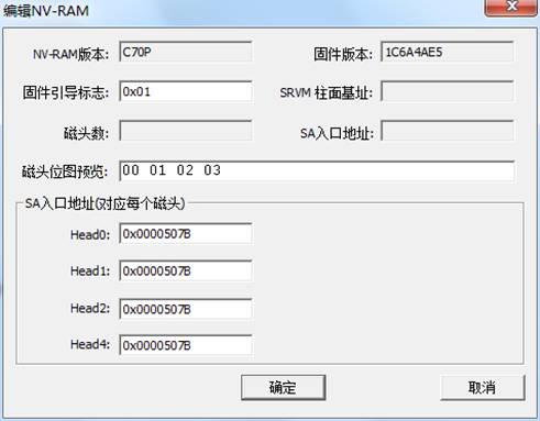
Figure2.2-5Edit the NV-RAM
After editing by users, click “OK” button to perform this operation, the operation result will display in the log page.
(d)Calibration of NV-RAM entry address
l Click“Calibration of NV-RAM entry address”menu,it will firstly pop up the working directory settings dialog box, users are asked to set the current working directory. It will pop up the “Calibration of NV-RAM entry address”dialog box after setting the current working directory by users, as shown in figure2.2-6.
Dialog box can be divided into the following parts:"Setup Mode", "Setup Range" "Setup Time" and "Set directory", but “Setup Mode ”is only effective to “SA entry address”. “Setup Directory”is used to save the current information of NV-RAM so as to recover NV-RAM in case calibration fails.
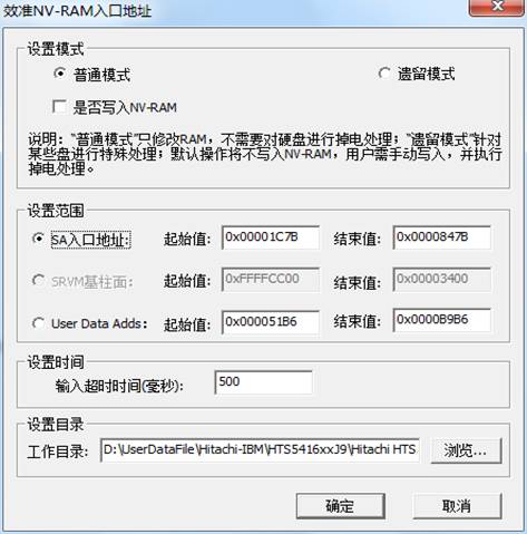
Figure2.2-6 Calibration of NV-RAM entry address
1.)SA entry address
“Calibration of NV-RAM” is used to search the entry address of NV-RAM and adjust it to the correct value , "Setup mode" can be divided into "Normal mode" and "legacy mode", the former uses the unified approach to deal with all the hard disks, when hard disk is busy with no process of reset, the speed is faster. The later is the unique MRT function that especially deals with the hard disk, when hard disk is busy with the operation of hard reset, the speed is slower. If users use the normal mode, it can't calibrate, users can try to use the legacy mode. If users check “Whether to write into NV-RAM ” as the entry access of calibration, the program will write the correct result into NV-RAM if it turns out a success, and the hard disk will be re-recognized. The execution result will display in the log page.
2.)User Data Adds
“User Data Adds”is used to search the entry address of user data and adjust it to the correct value. The program adjusts the entry address of user data area in NV-RAM, since after modifying the NV-RAM, the hard disk need power down and reboot, and it can be effective. Thus, this process will repeatedly modify NV-RAM and execute the operation of power down and rebooting to the hard disk until the 0 sector in the hard disk can be read. If users can’t make sure the head performance of HDD or the statue of disk, please use the function cautiously.
(3)Repair NV-RAM
“Repair NV-RAM” this function repairs only for the hard disk with NVRC module among 3.5 HDD serials.
(4) Module Object Backup
“Module Object Backup”saves all the normal modules among HDD as the file(As shown in figure2.2-7).
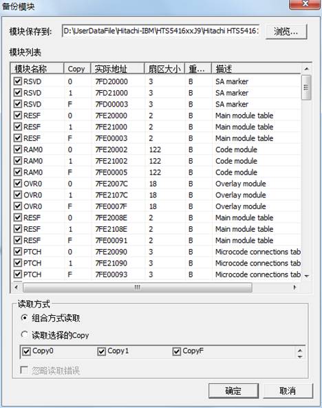
Figure2.2-7(Module Object Backup)
Users can set the save folder, also selectively check modules need to be saved. In addition, users can select the Read Mode, when “combination mode” is selected——the program will firstly read Copy0, if Copy0 reads wrong, it will read the corresponding sector on Copy1, finally it will combine with the correct data into a file, “Read Selected Copy ”——the program will backup the corresponding Copy checked by users;if users check “Ignore Error”, the program will save the data as the file whether to read right or wrong.
After setting the Save Option, click “OK” button to perform this operation, the execution result will display in the log page.
(5)Module batch write
“Module batch write” will write the Save Module into HDD, as shown in figure2.1-8.
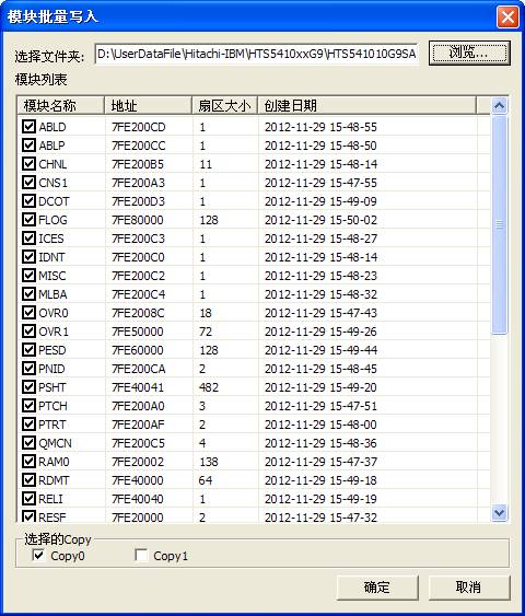
Figure2.2-8(Module batch write)
If users have set the working directory, the program will open the current working directory by default; otherwise the default is Drive C. There are three kinds of backup folders to choose: Copy 0, Copy1, Copy F, according to the settings when users save the module,after selecting the backup folder , list all the modules that have already been backed up, and then users can selectively check the modules need to be written into.
(6)SA Structural Testing
“SA Structural Testing” is used to test whether each module can be read normally, the test result will display in the log page.
3. Kill head
“Kill head”is used to kill the magnetic head(As shown in figure2.3-1).Before killing the head, users need to open Scan Disk Program to view the basic statue of HDD.
If the hard disk write function is off, we need to manually modify the start logo of NV-RAM, the method of modifying is; Open NV-RAM, and then modify the firmware boot flag, the flag is in the position of 0x09 and occupies one byte. The flag indicates HDD has how many heads, 0 indicates there is only one effective head, larger than 0 indicates there are many heads.
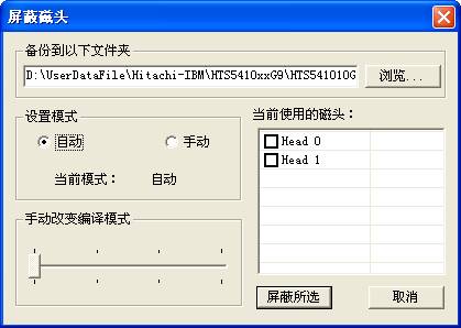
Figure2.3-1 Kill head
Users can check the head needs to be killed according to the practical situation, “Setup Mode”can select“Automatic”or“Manual”;“Automatic”mode defaults to 01 mode for the program with two heads, defaults to 02 mode for the program with more than two head. “Manual”mode, Users can manually change the translation mode, there are 01、02、03、12 and other modes to select, the corresponding scale is from 0-3.
After setting the parameters, click “Kills the selected”, the program will automatically finish all the function, the operations, result will display in the log page. Finally users need to manually carry on formatting to make HDD work normally.
4 Defect Operation
Defect operation" provides the function of "View P-List", "Clear G-List", “Edit G-list” "G-List to P-List" function(As shown in figure2.4).
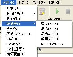
Figure2.4 Defect Operation
(1)View P-List
“View P-List”provides a view to the P-list, it will firstly ask users to save the defect list that has read((As shown in figure2.4-1).P-List detects are the factory defects,arranged according to CHS address, HDD will initialize the translator according to P list defects.
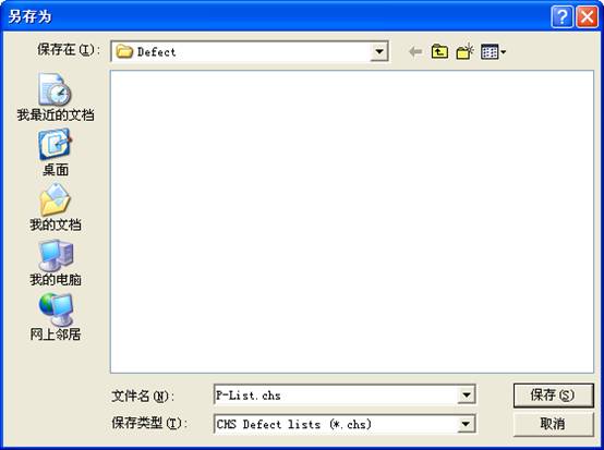
Figure 2.4-1(Save P-List)
After the completion of saving the P-list, it will display all the “Basic defect lists” in the hard disk(As shown in figure2.4-2).
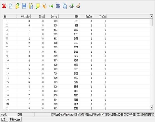
Figure2.4-2(View P-List)
(2)Edit G-List
“Edit G-List”is used to display HDD G list defects and provides the function of editing and modifying for users, after clicking “Edit G-List” button, it will pop up the Save Dialog box, as shown in figure2.4-3.
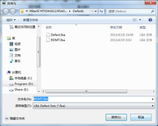
Figure2.4-3(Save G-List defects)
G-List defects are the defects arranged according to LBA address, G list defects are defects in the growth list,users are in the process of logical scanning or formatting, HDD will automatically add the defects to G list. Defects added to G list can use G-list to P-list and add to P list, and then after the process of formatting, defects inside P list will be killed.
After the completion of saving G-list, it will display all the HDD“G-list defects”(As shown in figure2.4-4).
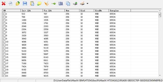
Figure2.4-4(G-List Defect)
(2)Clear P-List
“Clear P-List” will empty HDD “Basic Defect Table”. P-List is “Factory Defect”,which is the defect found by manufacturers to use the specialized test device, each HDD will set aside some extra and high-quality sectors when HDD enters the market after several steps of examination, when HDD starts, it will rebuild the translator according to P list defect, the defect address recorded in P list will be replaced by the extra sectors, only this can guarantee the capacity of HDD does not change. “Clear P-List” will release these defects, the exposed defect can be found by the logical scanning.
(3) Clear G-List
“Clear G-List” will empty HDD “Growth defect list.” These defects are caused by man-made mistakes in the course of using HDD, can be found in the course of HDD operation, can be found in the course of scanning test, or also can be found in the process of the automatic or use of specific formatting command to reallocate.
Defects recorded in G list can’t hide the mistaken sectors.
(4)G-List to P-List
“G-List to P-List” is used to turn “Growth defect list” into “Basic defect list”.
Only defects in P list can hide the mistaken sectors, thus, it generally firstly uses the logical scanning to add the scanned defects to G list, and then performs G-list to P-list, defects in G list hide in P list. At the end, the formatting is executed, like this; the mistaken sectors will be replaced by the normal sectors.
5. Formatting
Formatting is used for the lower level format to the hard disk, as shown in figure 2.5-1. Users can specify the area need s to be formatted.
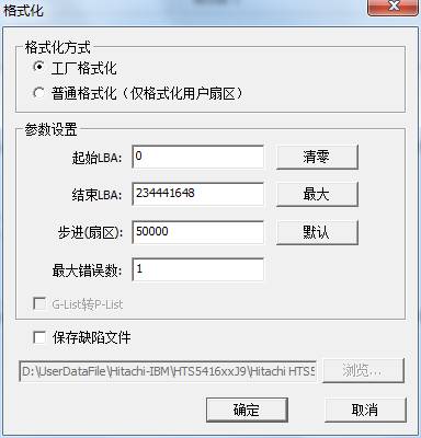
Figure 2.5-1(Formatting)
“Factory Format”users can specify the starting LBA and the ending LBA as well as how many sectors to be formatted per time. The maximum number of error is used to mark the allowing wrong number of sectors, when this maximum number of error is exceeded, it will stop formatting.
When users check “Save Defect File” and specify the correct saving path, click “OK” button to format HDD, after the completion of formatting, it will display all the defects of HDD, as shown in figure 2.5-2. Attention please, all data will be lost after HDD formatting.
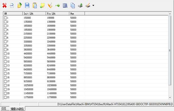
Figure 2.5-1(Defects records in the process of formatting)
Users can load the displayed defects into G-List.
6. Clear S.M.R.T
Self monitoring, Analysis and Reporting Technology (SMART) are designed to protect users’ data and reduce the possibility of sudden system downtime caused by the expected degradation or the malfunction. By monitoring and storing critical performance and standard parameters, SMART device attempts to predict the time close to the condition of degradation and malfunction. If the host system knows a non-reliable condition, the host system is allowed to warn users the risk of closing to lose data and suggests users to take appropriate measures.
After the execution of "Clear the S.M.R.T", it will empty all the recorded parameters.
7. Load LDR
Loading LDR is used to load the basic module tables from files(as shown in figure2.6-1).
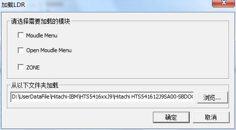
Figure 2.6-1(Loading LDR)
The loading result will be display in the log page.
8. Editing HDD ID
“Editing HDD ID”is used to modify“Firmware Version”、“Model”、“Series Number”、“Capacity” and other information of HDD,(as shown in figure2.7-1).
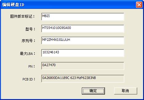
Figure2.7-1(Editing HDD ID)
2.2Tools
“Tools” menu has:"Firmware Object View", "Standby and Reset", "User Sector Viewer”, "Logical Scan", "CHS defect Editor", "LBA defects Editor" and other submenus.(As shown in figure2.2).
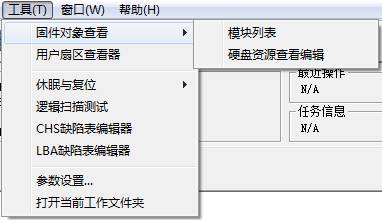
Figure2.2(Tools)
1. Firmware Object Viewer
(1)Module List
Module list is used to display, modify each of module information inside the hard disk. As shown in figure 2.2-1.
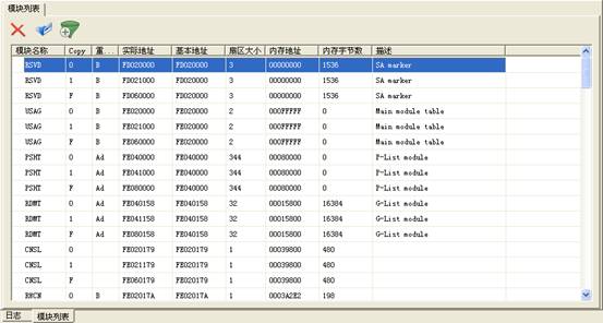
Figure 2.2-1Module List
Double click any line to load the module into 16 Hex Editor, as shown in figure 2.2-2. Users can modify, save, and write into the hard disk and other basic operations.
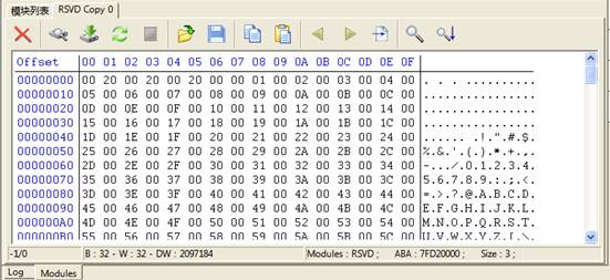
Figure2.2-2 16Hex Editor
(2). View and Edit Hard Disk Resource
“View and Edit Hard Disk Resource” is used to view the information of each hard disk firmware and edit the firmware resource, as shown in figure 2.2-3.
The function can be divided into two parts: Module and RAM/NV-RAM. Module will display all the firmware information of the hard disk, RAM/NV-RAM will display the information read from the chip, including the information inside ROM, NV-RAM, RAM.
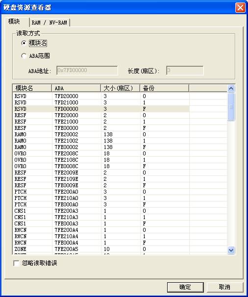
Figure2.2-3 View and Edit HDD Resource
Users can select any line, or use ABA range to manually input ABA address and length. Address is expressed in hexadecimal, start with 0x, length is expressed in decimal notation,click “OK” button to load this module, or double click any line in the list to load this module. After loading the module, it can be modified. About 16 hex editor, refer to the aforementioned.
3. Standby and Reset
“Standby and Reset”provides the routine operation on the hard disk, please refer to “The Main MRT Program Description” about “Soft Reset”, “Hard Reset”, “Reset”, “Standby”.
4. User Sector Viewer
“User Sector Viewer”is used to view and edit in the specified sector. As shown in figure 2.2-4.
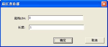
Figure2.2-4 View and Edit User Sector
After users filing in the starting LBA and the length, click the "OK" button to read out the designated sector, edited in the Hex Editor.(As shown in figure2.2-5)
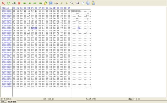
Figure2.2-5(User Sector Viewer)
4. Logical Scanning
“Logical Scanning”is used to carry on the test of reading and writing to HDD, as shown in figure 2.2-6. Users can set “the starting LBA”、“the end LBA”and “Block Size”,there are these selectable ”Block Size” 1、32、64、128、256(the default block size). Timeout agreement can let users themselves define the time of reading, time of writing timeout, time of commanding to send timeout. After setting parameter, click “OK” button to begin to scan, the process of scanning is as shown in figure 2.2-7.
When users check “Save bad sectors to the file of defect table”, the program will scan the final result and save it as the file, and it will display in “Editing LBA Defect” page, as shown in figure 2.2-8.
To those bad sectors that it may recover normally after the execution operation of erasing, so the program provides the modification options, when users check the corresponding options, it will perform the corresponding modification operation.
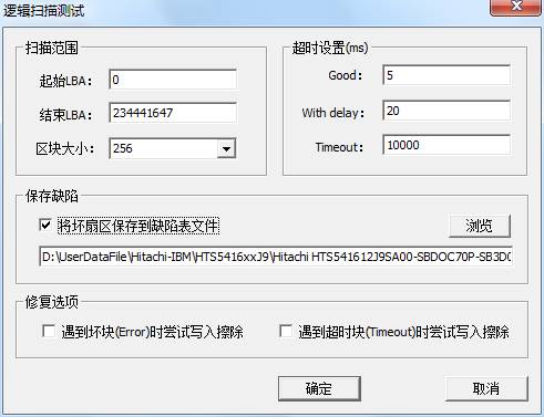
Figure 2.2-6(Setting Dialog Box of logical scanning)
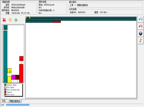
Figure 2.2-7(Logical Scanning Process)
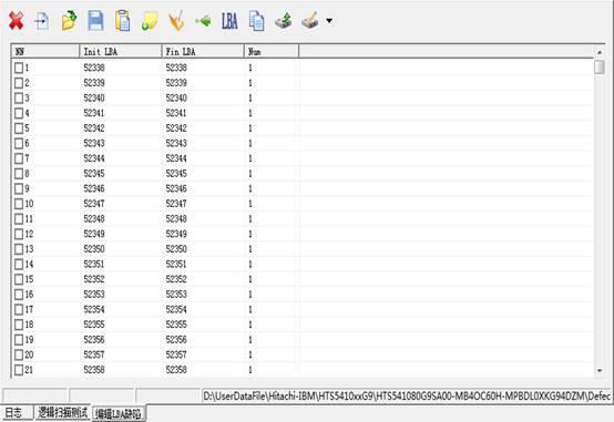
Figure2.2-8(Logical Scanning Result)
4. Parameter Settings
“Parameter settings” is used to set ATA timeout agreement(As shown in figure2.2-6)
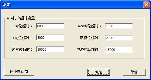
Figure2.2-6(Parameter settings)
5. Open the Current Working Directory
“Open the Current Working Directory” is used to locate in the current working directory in use; this working directory holds all the information on the current hard disk firmware.