Hitachi-IBM Firmware Instructions and the Operation after changing Hardware
These documents are derived from the MRT Firmware laboratory.
For more information, please visit our website.
1. Hitachi Hard Disk Boot Process
The hard disk firmware guide program of the series of Hitachi-IBM is located in ROM chip inside PCB, including the servo part of the control of motor also in the ROM. But inside the NV-RAM stores the information of disk configuration, including boot label, head bitmaps, service area entry address, user area entry address, SA adaptation information and so on. The boot process is similar to the boot process of the computer. Firstly, initialized by the ROM power-on and guide NV-RAM from hard disk service area to load the necessary modules, such as ATA micro program modules, P-List, G-List, CHNL, ZONE and so on. These modules are loaded into RAM to be used by the hard disk during its working. As long as the following-up power is uninterruptible, information stored in RAM always exists.
So the servo system inside Hitachi-IBM hard disk most time will not work if the ROM is broken down, or to indicate the Busy lamp is always lighting. If NVRAM does not match HAD, it will result in hard disk knock on disk or unable to properly load modules.
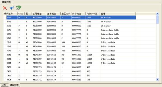
2. Parts of Hitachi Hard Disk Modules Description.
(1)CNS1 Modules:LBA
Old hard disk using C/H/S(Cylinder/Head/Sector)to search the address.
Magnetic head(Heads): Shows that the hard disk has several magnetic heads, or has several discs.
Number of cylinders( Cylinders):Shows the hard disk has several magnetic tracks on each side of the disk.
Number of sectors:Shows that there are several sectors per magnetic track, theoretically speaking, every sector (not a must) memories 512 bytes.4k technology for modern hard disk, every sector can store 4096 bytes.
Most of the modern hard disks are the equal density structure (outer magnetic track sectors are more than the inner sectors) and adopt linear addressing(LBA), namely taking the sector as the unit for addressing. In order to maintain compatibility, an address translator is installed inside the hard disk controller, which is responsible for translating the old 3D(C/H/S) into linear parameters (LBA).
Information recorded in CNS1 is necessary for the runnings of address translator, not only include the hard disk LBA information, but also include its capacity.
(2)RSVD: No records in the module table; mark the starting position of firmware zone (RSVD has no CopyF but has ACSII tables).
This module is used to mark the starting position of service area when the hard disk loading the module service area, it will first seek the starting address of the service area in RSVD, and then according to the address, the module among the service area will be loaded into RAM.
(3)USAG/RESF Module:The module allocation table of firmware (open module list), all module information are recorded on USAG/RESF modules and stored in the service area.
List of Hitachi-IBM modules above is loaded according to the USAG/RESF module, thus if not correctly read the USAG/RESF module, it will be unable to display the list of modules.
(4)CHNL/CHNM:HDD Hardware Adaption Parameter Table
Hardware adaption parameter including servo parameter, such as the motor speed, voltage and so on; the head amplifier parameter, the head amplifier is used to read and write the disk’s weak signals, and then deliver to the sensor after amplifying the signals.
(5)OVR0、OVR1 and RAMO:Micro Program Module(Overlay Firmware).
For the embedded system in the hard disk, NV-RAM directed by ROM from the hard disk service area (located in disc) loads the running modules into RAM. And micro program module records the necessary runtime parameter, and it cannot change during its runtime.
(6)IDNT:Model
(7)DDD0:DDD Log
(8)DIAG:Inside production date、model、 SN、 firmware version number、 interface type.
(9)SMRT:SMART Table
The purpose of self-monitoring, analysis and reporting technology is to protect the data of users and reduce the possibility of sudden system downtime caused by the expected equipment degradation or malfunction. By monitoring and storing critical performance and standard parameters, SMART devices attempt to forecast its close to the possibility of the time of degradation or malfunction condition. If the host system knows a non-reliable condition, it will warn users close to data loss risk and suggest users to take appropriate measures.
If one or more attribute values is less than or equal to their corresponding property limits, so the reliability of the equipment is near to degradation or malfunction conditions.
(10)PSHT: Factory defects table (Translator module), related to loading module list error.
These defects found by the manufacturer that use specialized test equipment, which are permanent defects after the completion of magnetic media. Non-manufacturers have no ability to cancel them, but to use special equipment to increase. Because G-list exists, generally speaking, there is no need to touch them.
(11)RDMT: Growth defect list, related to loading open module list error.
In the process of operation hard disk found these defects. They can be found in the formatting process, or in the process of automation or using specific formatting commands that command to do reallocation.
Defects encountered in Self-Scan of hard disk or in the process of its formatting will be recorded in this module. The hard disk will use the normal sectors to replace the error one to ensure its capacity unchanged
(12)SRVM:Ignore cylinder table (cylindrical defects table)
(13)ZONE: Area allocation table
Due to the adoption of the LBA addressing, addressing scope of each magnetic head is different; the ZONE module records the addressing scope of each head.
(14)RLBA: Extended firmware area distribution table
(15)ICES、PSWD、SECI:Cryptographic module
ATA document stipulates that manufacturers can provide the function of locking the hard disk, so the general hard disks can provide the function of setting a password, the password is divided into conventional password and manufacturer password. Conventional password is the way according to the regulations of the ATA document to get disk locked, and it can be divided into user password and master password. The master password can be used to get disk unlocked if in the situation that the user password is unknown. Manufacture password is commonly prescribed by each of their own hard disk manufacturers; Hitachi-IBM series hard disk passwords are generally stored among the modules of ICES, PSWD, SECI.
(16)RDM1:RDMT Alias
(17)RDM2:Copy of RDMT
As the G-List is very important, so Hitachi-IBM HDD has multiple backups for RDMT modules, there are RDM1, RDM2 in addition to Copy0, Copy1, CopyF.
(18)PDM1:PSHT Alias
(19)PDM2:Copy of PSHT
Since the P-List is very important, so Hitachi-IBM HDD has multiple backups for PSHT modules, there are PPDM1, PDM2 in addition to Copy0, Copy1, CopyF.
(20)ELG1: Defects Table Log
(21)EVLG: Defects Event Log
(22 PIDM:Module including PCB and HAD tag information
(23)MFGP:MFG Parameter --- containing the SELFSCAN parameter module
3.The operation of Hitachi hard disk should be done after change hardware.
3.1. Hitachi hard disk change circuit board
In the condition of determining the firmware version (ROM) and adapter (NV-RAM), users can change the circuit board. After change circuit board, SA entry address inside NV-RAM is not correct, and may cause the module cannot be loaded, and this moment you should calibrate SA entry address.
3.2. Hitachi hard Disk Change Heads
After changing the head, there is no need to do any operation, the premise is to ensure that the replacement of heads is correct.